This thread has been locked.

If you have a related question, please click the "Ask a related question" button in the top right corner. The newly created question will be automatically linked to this question.

MSP430FR5729: MSP430FR5729 restart problem

Part Number: MSP430FR5729
Other Parts Discussed in Thread: MSP430F5419A

Hi everyone,

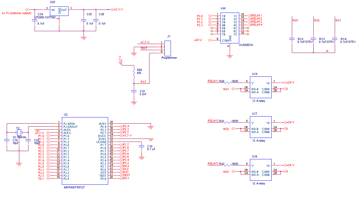
I am using MSP430FR5729 in my circuit. I am driving relays on MSP430FR5729 via ULN2003. Relays are switching on and off 230V power supply.

But i have observed one weired behaviour in which my controller getes restarted after some switching operations. I tried strong pull up on reset by replacing 47K with 10K but with no effect.

In my previous designs with MSP430F5419A i have done the same thing but have never came across such issues.

Please suggest for the same. Thanks.

Regards.

  • Hello Pallav,
    Please check the value of SYSRSTIV for determining the cause of RESET and then take care for it accordingly.

    Regards,
    Vikas Chola
  • Dear Vikas,

    Thanks for the reply. I have already checked the same it is due to reset. For the same reson i dis the 47k to 10k change.

    Regards.
  • Hi Pallav,

    Please provide a board schematic and oscilloscope shots of the VCC and RST line during the unexpected behavior.

    Regards,
    Ryan
  • Hi Ryan,

    I observed both signals but there is no fluctuations on both Vcc & RST.

    Signal is 3.3 V constant. That is the reason i am confused. Actually there is no change on VCC or RST channel but controller gets restarted.

    Regards.

  • Hi Pallav,

    This would seem to indicate a software-controlled reset as compared to one instigated by hardware. Please provide the exact value of SYSRSTIV upon device start-up after the unexpected reset occurs. A board schematic would still be helpful and please also state what your system's operating frequency is, supplying initialization code if possible.

    Regards,
    Ryan
  • Hi Ryan,

    I have used function

    void Reset_ISR(void)
    {
    switch(__even_in_range(SYSRSTIV,SYSRSTIV_PMMKEY)
    {
    case SYSRSTIV_NONE: break;
    case SYSRSTIV_BOR:break;
    case SYSRSTIV_RSTNMI:break;
    }
    }

    in which it enters the function SYSRSTIV_RSTNMI.

    Secondly i will provide you schematic in day or two.

    As far as operating frequency is concern i have used 8MHZ as a frequency.

    Initialization code is as follows.

    void main( )
    {
    // Stop watchdog timer to prevent time out reset
    WDTCTL = WDTPW + WDTHOLD;
    //=================== DO pins ==========================================================
    P2DIR |= BIT2 + BIT3 + BIT4;
    P2OUT &= ~(BIT2 + BIT3 + BIT4);

    P3DIR |= 0xFF;
    P3OUT &= ~0xFF;

    PJDIR |= 0x06;
    PJOUT &= ~0x06;
    //==========================DI pins ===================================================

    P1REN |= 0xFE;
    P1OUT &= ~0xFE;

    P2REN |= BIT7;
    P2OUT &= ~BIT7;

    //===============Default clock settings===============================================================

    CSCTL0_H = 0xA5; // clock 8MHZ
    CSCTL1 |= DCOFSEL0 + DCOFSEL1; // Set max. DCO setting
    CSCTL2 = SELA_3 + SELS_3 + SELM_3; // set ACLK = XT1; MCLK = DCO
    CSCTL3 = DIVA_0 + DIVS_0 + DIVM_0; // set all dividers

    //=======================Uart setting================================================================

    P2SEL1 |= BIT5 + BIT6; // uart1 pin selection P2.5 ,P2.6
    P2SEL0 &= ~(BIT5 + BIT6);
    UCA1CTL1 = UCSSEL_2 | UCSWRST; // uart clock select
    UCA1BR0 = 4; // uart set at 115200,stop bit = 1, data bit 8, parity none
    UCA1BR1 = 0; // buadrate setting
    UCA1MCTLW = 0x5551; // set modulation from user guide, i.e Sx=0x55, Fx=0x5, UCOS16=0x01 = 0x5551
    UCA1CTL1 &= ~UCSWRST;
    UCA1IE |= UCRXIE; // receive interrupt enable

    //===================================RTC CONFIG===========================================
    RTC_SET("2017","1","1","01","00","00","0"); // 1 jan 2017 12 o'clock midnight sunday.

    //=======================================================================================

    delay(50000);


    __bis_SR_register(GIE) ; //Enable all interrupt

    while(1)
    {

    }

    Regards.
  • Hi Pallav,

    Thank you for providing the code, nothing appears to be out of the ordinary with the initialization code but I would like to point out that ACLK = DCO under this configuration (most likely just a comment mistake). Still waiting for the schematics.

    Regards,
    Ryan
  •  Hi Ryan,

    Sorry for the late reply. Please find attached schematic for the same.

    Regards.

  • Hi Pallav,

    VCORE requires a 470 nF capacitor and the ratio of VCC to VCORE should be more than 10 (both of these specifications are to be found in the datasheet), therefore VCC capacitance should be greater than 4.7 uF. The LFXT load capacitors are also smaller than usual but this depends on the type of crystal being used, your code should be implementing a fault flag loop to make sure that it starts up properly.

    Regards,
    Ryan

  • Hi Ryan,

    We have tried .5uF @ Vcore and 10uF @VCC but with no change.

    LFXT load capacitors are depending on my crystal datasheet. We have tried other crystals with 24pf also but with no effect.

    Last point i could not understand. Can you please explain?( your code should be implementing a fault flag loop to make sure that it starts up properly)

    Does that mean we should try for proper start up i.e.

    PJSEL0 |= BIT4 + BIT5;

    CSCTL0_H = 0xA5; // clock 8MHZ
    CSCTL1 |= DCOFSEL0 + DCOFSEL1; // Set max. DCO setting
    CSCTL2 = SELA_3 + SELS_3 + SELM_3; // set ACLK = XT1; MCLK = DCO
    CSCTL3 = DIVA_0 + DIVS_0 + DIVM_0; // set all dividers
    CSCTL4 |= XT1DRIVE_0;
    CSCTL4 &= ~XT1OFF;

    do
    {
    CSCTL5 &= ~XT1OFFG;
    // Clear XT1 fault flag
    SFRIFG1 &= ~OFIFG;
    }while (SFRIFG1&OFIFG); // Test oscillator fault flag

    We have tried this also with no effect.


    Regards.
  • Hi Pallav,

    Yes I was referring to the oscillator fault flag test which had not been provided before, this at least shows the LFXT starting up properly. Oscilloscope screenshots of the issue have yet to be provided.

    Regards,
    Ryan
  • Hi Ryan,

    What signal i should be providing?
    1. VCC
    2. Reset
    ??

    Regards.
  • That is correct Pallav, Vcore and LFXIN would also be appreciated.

    Regards,
    Ryan

**Attention** This is a public forum