This thread has been locked.

If you have a related question, please click the "Ask a related question" button in the top right corner. The newly created question will be automatically linked to this question.

MSP-GANG: errors 14 and 23

Part Number: MSP-GANG
Other Parts Discussed in Thread: MSP-FET, , MSP430F47197, MSP430F6736A

Hi

I'm using an MSP-FET to successfully load my firmware into the MSP430-F6736A on my custom board.
I'm using a custom JTAG cable that i made up from a 8 wire ribbon cable.
This works with no problems.
So i can assume my cable is fine (length 180mm).

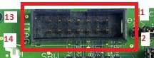
This is the JTAG connector on my board....each track goes to the applicable MSP430 pin.

I am now wanting to load my firmware using an MSP-GANG and using the same cable as above.
The board has its own power (naturally) and the GANG has been set up to NOT supply power to target.
When i try and load the MSP I get error 14 "Vcc too high"...but when measured, Vcc is 3.25 so clearly its not too high so the error message must mean something else.
As a test, I did lower the board voltage so Vcc was 2.8V but then i got an error 23 (Failed to initialise MCU) which i would think is quite correct as that voltage is too low.
I did try lowering the data rate but that still gave the same error 14.

I know the GANG is not faulty because i've successfully read the flash on an MSP430F47197 using a std JTAG cable and TS430PZ100A.

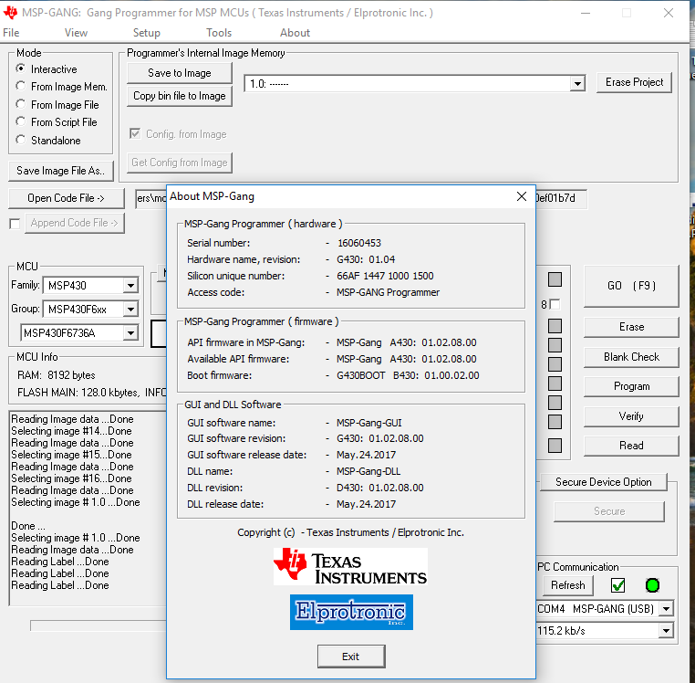
This is the GANG setup..


My Question is: What could be wrong??

thanks

  • Hi moshe,

    For the board with normal power, can you take a meter and probe on the exact Vcc pin where you are connecting your custom JTAG cable? Is that where you were measuring the Vcc voltage before (at the actual pin used for the JTAG connector Vcc), or were you measuring elsewhere on the board? You may also want to try to probe the voltage at the MSP-GANG side, the pin that connects to your custom cable, to see if the correct voltage also appears there - it should be pin 4 of the JTAG connector.

    Can you double-check that you have Vcc on your board connected to pin 4 of the MSP-GANG JTAG connector, and that you do not have anything connected on pin 2 of the MSP-GANG JTAG connector? I'm asking because often with custom cables, there is not the key-ing that you get on the standard JTAG cable, so it can be easy to have the connector accidentally be flipped. Make sure when referencing pin 2/4 on the MSP-GANG that you are looking in reference to where the key slot is on the JTAG connector on the MSP-GANG - see image below, where the key is on the top:

    Regards,

    Katie

  • Hi Katie

    Thanks for your response.

    The Custom cable i am using DOES WORK with the MSP-FET so unless the MSP-GANG JTAG connections are different, there is no reason why it shouldn't work with the GANG.
    And, looking at slau358m.pdf (p124) i see the connections are the same...so the cable & the connections aren't the issue in this case.

    I also did measure the Vcc on pin4 at the board and it was 3.28V - so clearly the voltage on the board isn't the issue either.

    And yes, pin2 of the GANG is not connected to anything.

    And finally...i did check the Vcc value on pin4 AT the GANG...that was 3.25V

    So given all the above, what should i check next?
    Or, what setting should i ensure has been set on the GANG?

    Perhaps it may also assist in knowing what the GANG message actually indicates when it displays the error "Vcc is too high"? Too high compared to what? Or to high in absolute terms?

    thanks

  • Hi Katie

    Following on from the above....and for anyone else following this thread.

    After a bit more reading and searching and theorising, i took the following courses of action:

    I added a 100 ohm resistor on the Vcc wire GANG to PCB so that the Vcc the GANG saw was less than 3.3V My rationale for this was the error message saying the Vcc was too high (Error 14) meaning what it thought it saw was more than 3.6V even tho it was just 3.25V.
    So after adding the resistor the message changed to ‘MCU initialisation error’ (Error 23).
    And now by manipulating the voltage value on the GANG screen I could go from Error 14 to Error 23 to Error 13 (Vcc too low)…so far so good..now to tackle why the GANG is not initialising the MSP!

     After more reading I came across a post for spy-by-wire which mentioned the CAP value on RESET for spy-by-wire in the user guide…so I thought I would see if there is anything about 4 wire JTAG & sure enough there WAS! Chapt 2 of the MSP430 user guide (SLAU208P.pdf)

    The recommended max value is 10nF but I have a 0.1uF on the RESET line (for a reset switch).

    So i removed that cap & placed a 10nF cap on the RESET wire from the PCB to the GANG….and voila…it worked!

    So now two observations:
    1. There is no need to twist any wires between the GANG and the custom board.
    2. There is no need to use a 8 wire or even 14 wire ribbon cable as i used 8 independent wires.

    And now a question:
    1. Why does the GANG see a voltage in excess of 3.6V when the real voltage is only 3.25V???
    2. What exactly is the GANG trying to do when it issues the error 23?
    3. Why does the cap on the RESET line affect the operation so drastically??

    here is the requisite pic....

  • Hi moshe,

    Thanks for doing some additional tests and providing more information.

    moshe jacobson18 said:
    1. Why does the GANG see a voltage in excess of 3.6V when the real voltage is only 3.25V???
    2. What exactly is the GANG trying to do when it issues the error 23?
    3. Why does the cap on the RESET line affect the operation so drastically??

    1. I am unsure why you are seeing a higher voltage when what you measure is 3.25V. Can you please share the MSP-GANG FW version? (in the GUI go to About >
    About and share a screenshot - this will show us the FW version in the MSP-GANG, the MSP-GANG HW version, as well as the GUI version being used). Then we can see if we are able to reproduce your issue with the same version. Additionally, you may want to test with the latest version 1.2.8.0 from www.ti.com/tool/msp-gang to see if you observe the same behavior. 

    2. Error 23 "MCU device initialization failed" is an error message that means that the MSP-GANG tried to establish a JTAG or SBW connection with the MSP430 device, but it was not able to connect to the device. Basically what is happening is that the MSP-GANG is performing the JTAG/SBW entry sequence on the TEST & RST lines and doing the connection sequence (there is way more information on JTAG connection in www.ti.com/lit/pdf/slau320 if you are curious).

    3. The RST line capacitance has a dramatic effect because this line is one of the two lines (TEST and RST) that are used to perform the JTAG or SBW entry sequence to establish the connection with the device, and this entry sequence is timing sensitive. If you look at the required JTAG connections listed in the Hardware Tools User's Guide www.ti.com/lit/pdf/slau278 figure 2-1 Signal connections for 4-wire JTAG Communication, this shows the required JTAG connections. You can see that the capacitor on the RST line C1 says to see notes B and E. Note E says " When using a device the supports 2-wire JTAG communication in 4-wire JTAG mode, the upper limit for C1 should not exceed 2.2nF. " Therefore, for reliable behavior with TI tools, you should not use RST line cap greater than 2.2nF on your device - the cap used before was outside of the spec for JTAG communication (and 10nF is still too high). For the F5xx/6xx user's guide www.ti.com/lit/pdf/slau208 that you mentioned, I'm guessing the statement you found about 10nF was coming from Table 1-3 Connection of Unused pins. However, for RST this actually says 10-nF (2.2nF) pull-down and has a footnote (3). Footnote (3) makes the same statement as the hardware tools user's guide that I linked above, that you should not use greater that 2.2nF if you are trying to program the device with the MSP-FET or MSP-GANG programmer.

    The reason this cap is so important is because the JTAG entry sequence is timing sensitive. If you see the JTAG guide www.ti.com/lit/pdf/slau320 figure 1-12 you can see the JTAG access entry sequence, along with sequences for SBW, BSL, and other modes. If the timing is not just right on this line (e.g. if the cap is too large) you can have issues with the device not actually entering JTAG mode. That is why changing the RST line has such a dramatic impact. To be honest I'm very surprised that the setup you had before worked with the MSP-FET, but it was outside the recommended value for MSP-FET as well.

    Regards,

    Katie

  • thanks Katie...i'll get those screenshots to you in a few hours.
  • Hi Katie

    You really are very good & absolutely deserve your Guru status!

    I gave you a bum steer with the pointer to chapt 2 of MSP430 User guide....it SHOULD have been to Chapt 2 of the Hardware Tools user guide (slau278aa.pdf) fig 2-1  (i thought note E didnt apply & thus 10nF was the recommended value).

    I missed that entry in the table 1-3 in the MSP430x6xx user guide slau208p.pdf - my bad. So i will most definitely change to 2.2.nF

    Regarding the issue of external pullup on pin RST/NMI - table 1-3 in slau208 says its required, but then a little further on in section 1.7 (p71) it says " NOTE: All devices except the MSP430F543x (non-A devices) have the internal pullup enabled. In this case, no external pullup resistor is required."...so is it required or isnt it required on an MSP430F6736A??

    Below is the screenshot from the GANG...this issue with the misreading of voltage i really do need to resolve.

    thanks in advance

  • Hi Katie

    In addition to the previous message, and it may aid in resolving the issue..... i have repeated the below sequence consistently and the GANG remains connected to my self-powered board continuously throughout the sequence & that connection is via 8 individual wires.

    So:

    1. I disconnect the GANG from the PC & then remove power from the GANG & wait a few secs.

    2. Reconnect power to the GANG & then reconnect the GANG to the PC.

    3. Connect Pin4 on the GANG to my board via a 200 ohmn resistor. Voltage at pin4 is 3.238V.

    4. Set Voltage on the PC (interactive software) to 3.2V

    5. Read or press F9 - downloads perfectly.

    6. Remove the 200 ohmn resistor. Voltage at pin4 is now 3.254V

    7. Read or press F9 -again downloads perfectly.

    8. Repeat step 7 a few time - downloads perfectly every time.

    9. Repeat step 1.

    10. Repeat step 2.

    11. Connect pin4 to my board without the resistor. Voltage at pin4 is 3.254V

    12 Read or press F9. ERROR 14.

    13. Repeat step 12 a few times...ERROR 14 every time.

    14. Set voltage on the PC program to 3.6V and press F9...still ERROR 14.

    15. Reinsert 200 ohmn resistor & keep voltage at setting at 3.6V. Voltage at pin 4 now 3.238V

    16. Press F9 - downloads successfully.

    17. Reduce voltage setting to 3.2V and press F9 - downloads successfully.

    18. Remove the 200ohmn resistor. Voltage at pin 4 now back to 3.254V.

    19. Press F9 - downloads successfully!!!

    So there is something very very odd here.

    And again, i really do need to resolve this.
    Why do i need this issue resolved? Because the board is going to be going into production and the GANG will be used to program the MSP on it and i can't expect the technicians to fiddle with on/off board resistors & weird operating procedures.

    thank you in advance

    moshe

  • Hi Katie,

    For your awareness, I've linked to another recent thread that seems to be related.

    Regards,

    James

    MSP Customer Applications

  • Hi moshe,

    The external pull-up resistor is still recommended during programming, even though there is an internal one on these parts. For ruling everything out, can you do your test with this resistor populated?

    I have looped in our MSP-GANG designers as well to try to get more information on how the Vcc checking is performed to try to shed some light on the strange results you are seeing.

    Regards,
    Katie
  • Hi Katie

    The 200ohmn resistor mentioned above is on the Vcc track not the RST/NMI.

    Further, the sequence mentioned above was with both an external resistor ON AND OFF the RST/NMI track...and showed that the presence or absence of an external resistor didnt change an outcome.

    But i did some more testing...once i have the GANG downloading to the board, i repeat the downloading but progressively reduce the voltage setting on the program on the PC (Box 'Target's Power Supply' with 'external - in range +/- 0.3V', field "Voltage") down to 1.9V at which point the sofware responds "Vcc too high".....i then keep downloading but progressively INCREASE that voltage setting till it stops responding that the Vcc is too high and actually downloads to the board (normally a setting of about 3.4V).

    So there is an inconsistency in the program's response (and presumably also in the GANG) to that voltage setting......under a particular sequence a specific voltage setting downloads, and under another sequence it doesn't.

    As for the other issue i have with my FET....it may or may not be indicative of the same issue...its just odd (& irritating) that it only downloads on the 'retry'. My personal view is that the 2 issues may be related but the FET (&/or the software on the PC) is more robust.

    thanks
    moshe
  • Hi moshe,

    Let's back up a step. I remember that at the beginning of the thread you mentioned that you are able to easily program an MSP430 Target socket board, using the provided JTAG ribbon cable, using the MSP-GANG. If you do that test again, but making sure you use with the same power supply setup you are using on your custom board (externally powered +/-.3V and with the EXACT SAME supply device used that you have used on your custom board) do you still see success? Note that you'll have to make sure any jumpers on the target socket board are correctly set for external power.

    Why I think this could be worthwhile: If you do have success with that setup, that starts to indicate could it be an issue with the custom cable, or any of the components on the custom board, or a difference between the two MSP430 device families used rather than necessarily the MSP-GANG. Conversely, if it fails with that setup it starts to tell us the issue is more likely with the MSP-GANG or with something about the way the board is powered and that we may be able to reproduce it here on a TI board as well. So hopefully it could give us both a better direction to investigate further and narrow down possibilities.

    Regards,
    Katie
  • Hi Katie
    I connected the target socket board power to the same power track as the jtag pin connector on my board.
    I used my 8 individual wires as the jtag cable.
    The Gang programmed the chip on the socket board without any issues. Power Supply set on the GANG software as "External in range +/- 0.3V" with voltage "3.3V"
    Kept every setting (except the chip & the image) on the Gang the same and moved the wires from the socket board to the jtag connection on my board...and Gang responded with "Vcc too high".

    The voltage level is not the cause here yet it manifests as the cause.
    The cable is not the cause.
    The Gang is not the cause.

    So...what does this tell us? That in itself not a lot.

    However...
    I did try 1 further exercise. I connected a 330ohm resistor on the Vcc line between the Gang and custom board, and retried, and that did work with no issues.
    I then checked the voltage on either side of that resistor...GANG side 3.245V, board side 3.27 (much like previously above).
    i then moved the wires over to the target socket board and retried the exercise...Gang came back with "Vcc too low".

    So NOW i think I'm getting somewhere...
    The PC Gang software associates the MCU entered with a particular band of voltage on the Vcc pin.
    So for a MSP430F47197 a voltage of 3.27 is correct but for the MSP430F6736A its too high...and a voltage of 3.245 is fine for a MSP430F6736A but too low for a MSP430F47197.
    And that range setting of "+/- 0.3V" is apparently irrelevant.

    Therefore my conclusion is that the Gang software needs to be updated....would you concur?

    cheers
    moshe
  • Hi Katie and anyone else with a similar issue...

    Further to my message above, my must retract the last sentence!

    I found the issue here.
    Buried in my setup code was "PJDIR = BIT0|BIT1|BIT3;"
    I commented that line out and the problem disappeared!
    (and yes the FET was similarly affected albeit the message was different)

    thank you very much for trying.
    Moshe

**Attention** This is a public forum