This thread has been locked.

If you have a related question, please click the "Ask a related question" button in the top right corner. The newly created question will be automatically linked to this question.

MSP430F6736: max. modulator clock frequency if only using the decimation filter

Part Number: MSP430F6736
Other Parts Discussed in Thread: AMC1204, , MSP430F6779A

Hello,

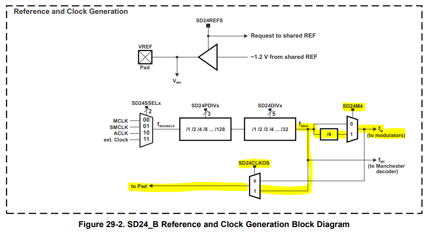
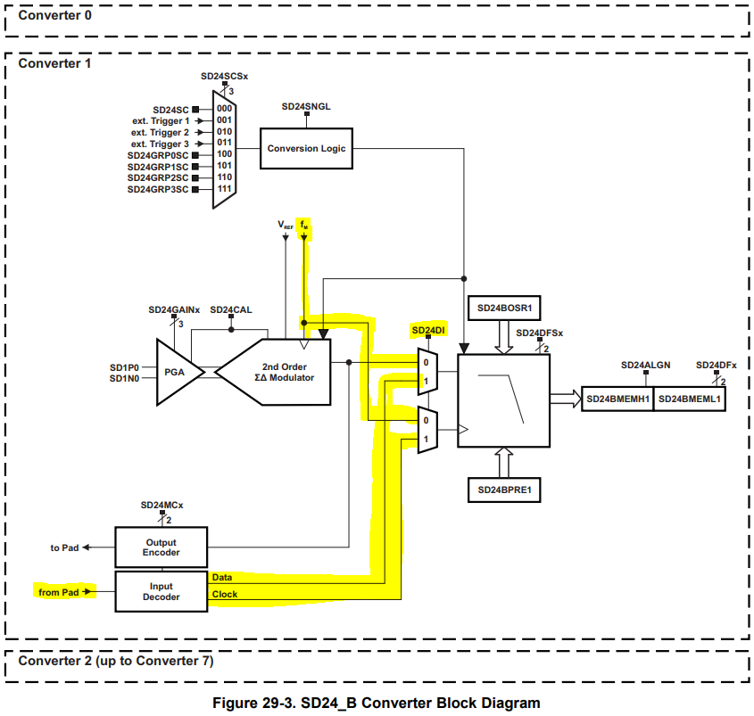
the max. frequency stated in the datasheet is 2.3MHz. But it is mentioned as "Modulator...". So, if I'll only use the decimation filter for an external applied bit stream via the portpins: What max. frequency I'm allowed to apply to the SD24 module, the same?

If it is allowed to use a higher frequency (e.g. 5MHz) and I want to use also a sigma-delta-modulator: I think I'll have to switch the frequency, before using the analog part.

Thanks in advance!

  • Hello Bjoern,

    I understand your question, and I don't see a maximum external modulation frequency given in the datasheet. Since there's only one maximum frequency of 2.3MHz provided in the datasheet for the SD24 module (which includes the modulator, the digital filter, and other related circuitry), I would recommend operating the digital filter at frequencies lower than 2.3MHz to guarantee proper operation. It will take some time, but I'll check on this use-case internally.

    Regards,

    James

    MSP Customer Applications
  • Hello James,

    thank you allready for the first informations!

    BTW: I maybe found something interesting in the datasheet of the AMC1204. On page 19 is written: "Also, the SD24_B converters on the MSP430F677x microcontrollers offer a path to directly access the integrated sinc-filters, thus..." So, I looked into the datasheet of the stated MSP430 and also here the max. frequency is 2,3MHz. The minimum frequency of the AMC1204 is 5MHz.
    So, I hope, there will be the possibilty to use it that way.
  • Hello Bjoern,

    I've dug much deeper into your question, and I've found that you can run the internal filter (but not the internal modulator) at frequencies higher than 2.3MHz. In my comments below, you'll see that these frequencies can reach 20MHz.

    Like you pointed out, the datasheet doesn't talk much about this type of configuration (using an external modulator with the internal decimation filter). I've submitted a request internally to address this.

    I did find several TI Designs that are using external SD modulators. Below, I've summarized how they were used and included links to each of their User's Guides.

    Multi-phase Energy Measurement with Isolated Shunt Sensors Reference Design (TIDA-00601)

    In Section 1.1 at the top of page 3, it mentions that no internal SD modulator can be used because the modulation clock frequency is higher than 2.3MHz. The AMC1304 is a precision isolated external SD modulator, and several are used here for the current channels. At the top of page 4, it mentions that the modulation clock must be between 5MHz and 20MHz for the AMC1304 to work properly. This clock can be supplied by the clock output of the SD24 module of the MSP430.

    For the SD24 module setup, refer to Section 3.2.1.1 on page 11. Here, the modulation clock (fM) to the trigger generator and the digital filters of the SD24_B ADCs is derived from system clock, which is configured to run at 19,798,016 Hz. Because the AMC1304 can support a clock from 5 MHz to 20 MHz, this clock can be used as the modulation clock for the AMC1304 without being further divided down. Similarly, the digital filters of the MSP430F67641s SD24_B ADC can also operate at this 20-MHz modulation clock frequency (unlike the internal modulators of the SD24_B ADC, which are bypassed in this application). In this design, the modulation clock used in the SD24_B is derived internally and output from the SD24_B module to the AMC1304 device.

    For the remaining two designs, they may utilize a different modulation frequency, so just search for "modulation" in their User's Guides to read more about it.

    Multi-Phase Power Quality Measurement with Isolated Shunt Sensors Reference Design (TIDA-01088)

    Magnetically Immune Transformerless Power for Isolated Shunt Current Measurement Reference Design (TIDA-01094)

    I did want to point out that this design uses a modulation frequency of around 5MHz supplied by the SD24 module to the external SD to reduce power consumption. See Section 2.2.1.1 in the User's Guide.

    Hopefully this helps!

    Regards,

    James

    MSP Customer Applications

  • Hello James,

    this sounds very good!

    Just one little topic is left open: With the MSP430F6736 there come three SD24-convertes.
    I will use one of the SD24-converter for the higherfrequency bitstream to be filteres via the SINC3-filter. I'd like to use a further SD24-converter to measure a voltage, using also the analog modulator. So, because the frequency for the bitstream is too high for the analog part, I'll have to switch back to a lower frequency (and therefore switching of the external higherfrequency bitstream).
    My questions:
    - Is it allowed, to do something that way or is there any reason, that will forbid this?
    - Are there special procedures or conditions, I'll have to consider?

    Bjoern
  • Hello Bjoern,

    As long as you're not using the internal modulators above the maximum frequency (which should be 2.3MHz), this should work but could be complicated to implement. At a high level, you'd have to make sure the internal modulator is off, increase the frequency, enable the bit stream from the external modulators, read the values, disable the external bit stream, reduce the frequency, enable the internal modulator, read the values, and repeat the process. I could see where this could impact your overall sampling frequency depending on how often you switch back and forth. If you need to measure voltage, why don't you use the ADC10 module as in the designs mentioned above? Typically, RMS voltage samples require less resolution than RMS current samples.

    I thought you could use the MSP430F6779A which has more SD24 channels but the internal modulation frequency would be the same across all channels in the entire module, so you'd face the same limitation.

    Regards,

    James

    MSP Customer Applications
  • Hello James,

    thank you so far. Just one further question: If I disable the modulator and enable it again, will I have to wait for a certain time for a valid VREF? I don't know, if VREF is also disabled during disabling the modulator. (I assume, that I won't switch between internal or external reference - it will allways the external reference.)

    So, looking at "MSP430F6736: settling- or on-time for external reference for SD24" I'll wait for 75µs - once.

    Regards,

    Björn

  • Hello Bjorn,

    Looking at the block diagram for the SD24_B in the MSP430x5xx/x6xx User's Guide, I realized that you could run the internal SD24_B clock at 5MHz (to provide the clock for the external modulators through the pad by setting the SD24CLKOS bit) and at the same time, set the SD24M4 bit to divide this clock frequency by 4 to source the internal modulators with a frequency (5MHz / 4) that's less than 2.3MHz.

    Next, you could clock the internal decimation filters externally by setting the SD24DI bit.

    EDIT: Setting the SD24DI bit to 1 switches to the external bitstream but the internal modulation frequency fM is still used to clock the internal decimation filters. See Figure 29-9 in the User's Guide for a detailed view of the input decoder. Please see my comments in my following post for additional clarifications.

    According to the User's Guide, setting the SD24DI bit disables the internal modulator, but I suspect  that it doesn't turn it off but that the data just doesn't reach the internal decimation filter. This way, you could switch back and forth between the internal and external modulators using the SD24DI bit without waiting for the reference voltage to stabilize.

    Regarding the reference, I would not recommend switching between an internal and external reference. It sounds like you're planning to use an external reference only, which is good. For calibration, it depends on the reference voltage, and if that's changed, it would affect your results.

    Bjoern said:
    So, looking at "MSP430F6736: settling- or on-time for external reference for SD24" I'll wait for 75µs - once.

    That's good. You'll only have to do this once when you initialize everything after the device powers up.

    Regards,

    James

    MSP Customer Applications

  • Hello James,
    thank you for this interesting approach. But I'm afraid, that will not work because of following statement in the Family-Datasheet (29.2.8) "...The incoming bitstream can be either synchronous to the modulator frequency fM or it can be a Manchester decoded bitstream...." So, looking also to the figure 29-9, this wouldn't work, I think.

    Let's assume I'll do it the way we explained first (switch off and on the internal modulator): Is there a time specified, which I must wait, until the VREF is valid for conversation?

    Regards,
    Björn
  • Hello Bjoern,

    That's a good observation, but I still think it will work. If fSD24 is output to clock the external modulators (when the SD24M4 bit is set to 0 then fSD24 = fM), then the incoming bitstream from the external modulators would be synchronous to the modulator frequency fM.

    Before using any of the modulators, configure the SD24 module. The order assumes that the external modulators will be used first.

    1. Make sure the external VREF is used by setting the SD24REFS bit to 0.
    2. Disable the internal modulators by setting the SD24DI bit to 1.
    3. Configure fSD24 to be 5MHz using the SD24SSELx, SD24PDIVx, and SD24DIVx bits.
    4. Set the SD24CLKOS bit to 1 which outputs fSD24 externally through PM_SDCLK.
    5. Make sure the SD24M4 bit is set to 0, since we want fSD24 to equal fM for now.
    6. Set the SD24MCx bits to 0x to allow the bitstream from the external modulators to be input to the internal decimation filters running at 5MHz.

    When switching to the internal modulators,

    1. Set the SD24M4 bit to 1, which divides fSD24 by 4 which sets fM to 1.25MHz which is less than the max 2.3MHz that the internal modulators can operate at. Also, the internal decimation filters are getting clocked at 1.25MHz by fM. Now, the external modulators are still getting clocked at 5MHz by fSD24 which is great.
    2. Enable the internal modulators by setting the SD24DI bit to 0. This routes the bitstream from the internal modulators into the internal decimation filters.

    When switching back to the external modulators,

    1. Set the SD24DI bit to 1 which disables the internal modulators.
    2. Set the SD24M4 bit back to 0 to increase fM from 1.25MHz to 5MHz.

    I would not recommend switching VREF off and on. The method described above will allow you to keep VREF on and not require you to reconfigure the SD24PDIVx and SD24DIVx bits for either internal and external modulator selection. According to page 80 in the datasheet, the SD24_B internal reference turn-on time (tON) equals 200us (SD24REFS = 0 -> 1 with CREF = 100nF), but your external VREF will most likely have a different settling time. You may find the following thread interesting.

    Please keep in mind that I didn't cover other important things that you'll have to consider like which triggers to use and when, whether the preload and OSR values will be the same or different for the internal versus external modulators, etc., but I hope this helps you get started with your implementation.

    Regards,

    James

    MSP Customer Applications

  • Hello James,

    thank you very much for this detailed discription. Unfortunately I implemented in the meantime your first approach (i.e. with switching the frequency and so on). Hopefully someone else could use it in the future!

    So, for my application: Also the function I use to switch between the frequency also sets everytime the external reference. (In the first step, it set's always the default (0b), which is fortunately the external reference.) To cut a long story short: At all times the external reference is switched on.
    In my case: When I switch back to the interal modulator (SD24DI = 0), must I wait for a dedicated time before I'm allowed to start a valid conversation? (e.g. The internal modulator has to come up, maybe the VREF applied to the modulator must become stable,...)

    Regards,
    Björn
  • Hello Bjorn,

    The SD24INTDLYx bits delays the interrupt service request for a completed conversion by up to four conversion cycles allowing the digital filter to settle. Keep in mind that this delay is applied each time the conversion is started OR when the SD24BINCTLx register is modified. The default delay value is four conversion cycles, which is what I'd recommend using to ensure everything's settled and valid before capturing the conversion data.

    Does this make sense?

    Regards,

    James

    MSP Customer Applications

  • Hello James,

    so the discarding of the first three samples (fourth is used as first sample) would be enough, to cover all delays and settle times?
    If this is true, this would be great, because I allready use this setting for all channels. ;-)

    Thanks!

    Regards,
    Björn
  • Hello Bjoern,

    That's correct. If I've answered your question, please click the green "This Resolved My Issue" button.

    Regards,

    James

    MSP Customer Applications

**Attention** This is a public forum