Other Parts Discussed in Thread: TIDM-TWOPHASEMETER-I2040, EVM430-F6779
Hi,
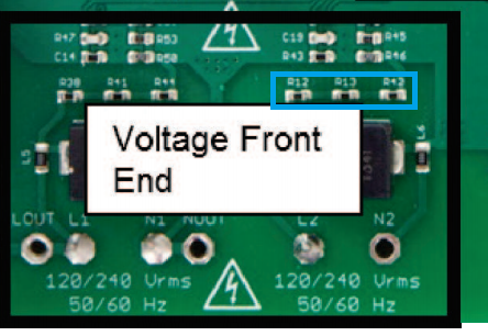
So i'm designing my 2 phases energy meter based on this application note : 
my question is related to the PCB design and the the clearance with the 220v:
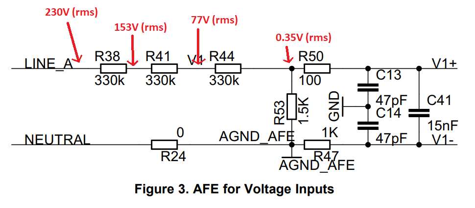
according to the Figure 3 page they used a voltage divider with R38, R41, R44 and R53 to drop down the voltage under 500v.
1/ i'm wondering why using 330k resistors (R38, R41, R44) instead of one 990k resistor ?
2/ above is a schema of the voltage divider where i add the RMS voltage value in each resistor, if we suppose that the input voltage is 230 V RMS.
when i checked the PCB design of the energy meter in the document i noticed that the clearance between the 230v and the neutral wasn't respected.
below a screenshot of the actual voltage divider inside the PCB :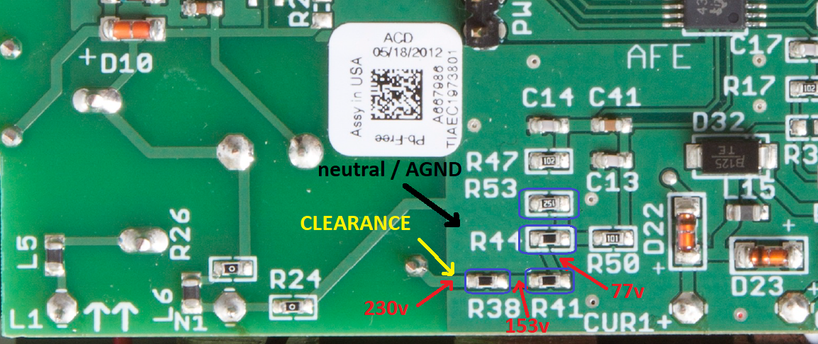
As you can see that the clearance between the 230V and the neutral is too small, normally it should be 1.25 mm ?
thanks,