This thread has been locked.

If you have a related question, please click the "Ask a related question" button in the top right corner. The newly created question will be automatically linked to this question.

MSP432P401R: CORTEX_M4_0: * WARNING *: The connected device is not MSP432P401R

Part Number: MSP432P401R

Hello,

My error is similar to https://e2e.ti.com/support/microcontrollers/msp430/f/166/t/554903

I created a custom pcb that has the msp on it, I believe my circuit is correct. I also removed the msp from another msp launchpad i had- just because i didn't want to order more during the holidays. 

Anyway, below is the printout. 

Here is my printout:

CORTEX_M4_0: * WARNING *: The connected device is not MSP432P401R

CORTEX_M4_0: GEL Output: Memory Map Initialization Complete

CORTEX_M4_0: GEL Output: Halting Watchdog Timer

CORTEX_M4_0: WARNING : On MSP432P401R hitting a breakpoint cannot be detected by the debugger when the device is in low power mode.

Click the pause button during debug to check if the device is held at the breakpoint.

CORTEX_M4_0: Flash Programmer: Erasing main memory

CORTEX_M4_0: Flash Programmer: Programming flash memory

I then am sent immediately to the default interrupt handler. 

I don't click resume at the start of the program.

I am not sure what to look for. I tried to probe the crystals to see if they were oscillating but on both my custom board and the launchpad i wasn't sure if my signal was correct... It appeared not to be doing anything BOTH boards. 

any tips on how to proceed with debugging would be great. I can try to get scope images up too, don't have them at the moment. 

Thanks!

  • Hello Kevin,

    Can you please share the schematics for your custom board? Also can you please elaborate on how are you connecting the JTAG to the custom board?
  • Hi! Thank you for replying. Here is the attached schematic. I referenced the schematic from the luanchpad rev 1 board by M. Stein. Unfortunately I could not find one for the msp432p401r rev c, red launchpad. 

    So attached is the schematic I currently have populated on my board. For JTAG I am using header pins to the jumpers of the mps432 launchpad. When I do a 'test connection' in CCS I get succeeded and can read the appropriate ID code. 

    MSP432p-for post.pdf

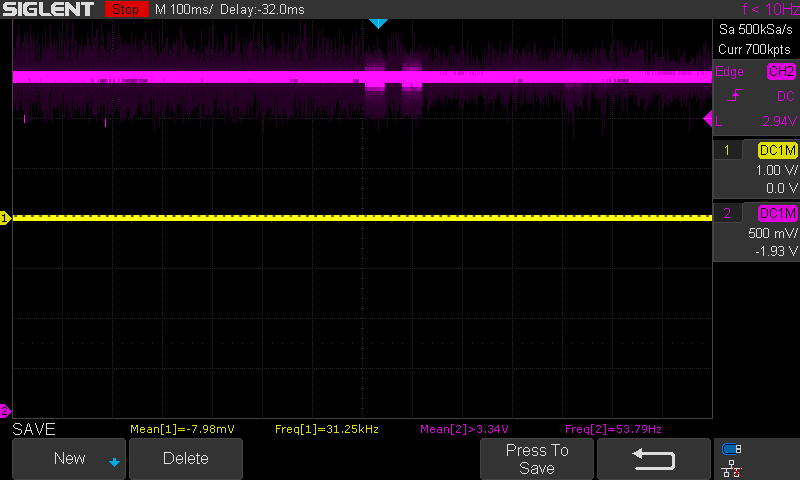
    The picture below is of the reset line while doing an upload to the board. 

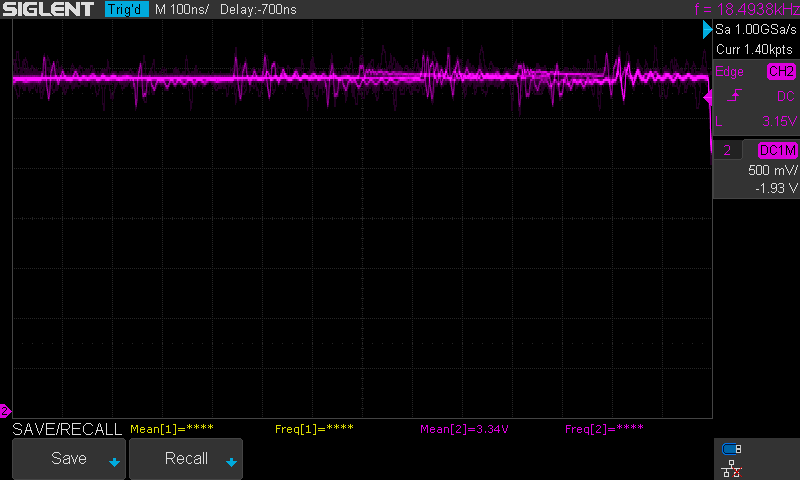
    The next image is when the device is constantly in reset, reset occurred on target. The reset line looks noisy. But i'm not sure what to look for. 

    Also what would the crystal look like on the scope? I wasn't sure and was probing my development board and i don't think i got a signal. 

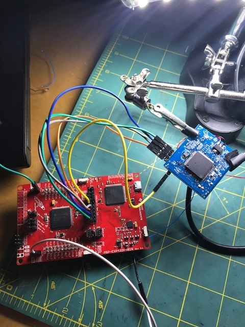
    above is my jtag connections from the dev board to the target via header pins

    test connection output:


    -----[Perform the SWD Mode Integrity test]-----------------------------------

    This test will read the IDCODE register 1 time.

    The IDCODE register value is 0x2ba01477.

    The SWD Mode Integrity test has succeeded.

    [End: Texas Instruments XDS110 USB Debug Probe]

    Thanks!

  • Hello Kevin,

    The JTAG header pins are on the wrong side of the jumper. Instead of being on the left side as shown in the picture, they should be on the right side of the header.

    Also it is very unclear why SWD Test Connection is working. I can only test it when I am in office on Wednesday.
  • You are correct! I just realized that. so when i got the test to work it was when they were in the correct location. sorry that must have been super confusing.

    OK SO i realized i didn't had not placed my 91k on pin 44 (DCOR), the inductor pin 12/14 (VSW, VCORE) with caps. but then i placed them now i get the following printout.

    CORTEX_M4_0: * WARNING *: The connected device is not MSP432P401R
    CORTEX_M4_0: GEL Output: Memory Map Initialization Complete
    CORTEX_M4_0: GEL Output: Halting Watchdog Timer
    CORTEX_M4_0: WARNING : On MSP432P401R hitting a breakpoint cannot be detected by the debugger when the device is in low power mode.
    Click the pause button during debug to check if the device is held at the breakpoint.
    CORTEX_M4_0: Flash Programmer: Erasing main memory
    CORTEX_M4_0: Flash Programmer: Programming flash memory
    CORTEX_M4_0: Flash Programmer: Verify error. Writing to Flash failed!
    CORTEX_M4_0: File Loader: Verification failed: Values at address 0x00000000 do not match Please verify target memory and memory map.
    CORTEX_M4_0: GEL: File: E:\CCS\test_blink\Debug\test_blink.out: a data verification error occurred, file load failed.


    Thanks!
  • Hello Kevin,

    I think, I would need to run some experiments when I am in office later this week to see what could be the issue. However a few things to check

    1. Does the Reset Pin remain High during the connection being made?
    2. Does the 3.3V supply remain stable?
    3. Does the VCORE show the correct voltage level during the connect?
  • Hi!
    (1) Yes the reset pin does remain high but looks like it has that ripple from the image above (purple line)
    (2) the 3.3V appears to remain stable through the scope, during entire operation and upload
    (3) so VCORE was shorted accidently at 3.3. Now its sitting at 1.28V which is consistent with the red dev board.

    so after fixing (3) the VCORE voltage I was able to get the board to take some code. It still says
    CORTEX_M4_0: * WARNING *: The connected device is not MSP432P401R
    CORTEX_M4_0: GEL Output: Memory Map Initialization Complete
    CORTEX_M4_0: GEL Output: Halting Watchdog Timer
    CORTEX_M4_0: WARNING : On MSP432P401R hitting a breakpoint cannot be detected by the debugger when the device is in low power mode.
    Click the pause button during debug to check if the device is held at the breakpoint.

    and stuck in reset. So I was curious what would happen if i initialized pins as GPIO for port 9 (my heartbeat led pin). I can correctly see that the registers change and indeed my led turns on. I tried to disable interrupts to force the reset from happening without luck.

    so a few questions arise:
    1) why does JTAG say that the ID of the m4 is correct but still says not msp432p401r?
    2) how can i get out of the reset?
    3) what is causing the reset?
    4) whats causing the first warning: the connected device is not msp432p401r?
    5) what should the reset line do?


    thanks for the tips any more that come to mind i'll do my best to document the progress.
  • Hello Kevin,

    With the VCORE shorted to 3.3V, it could be possible that there may be some damage to the device. Can you replace the MCU with a fresh device on the fixed board and then try the same process?
  • Hi
    It must be a hardware issue on my end. I replaced the chip. prior to programming any flash the vcore was not 1.28v after trying to flash it went to 1.28v. I am also still getting the same warnings as before.

    What should the reset line be doing?

    thanks.
  • Hello Kevin

    The Reset line must remain high during the programming of the device. I can check the behavior on a blank Launchpad w.r.t to the Vcore, but AFAIK it must remain at 1.2V when powered up.
  • Hello Kevin,

    I wanted to check if the issue is resolved?

  • final embedded smart_watch.rarnot yet. I didn't have any more chips, and I didn't have the right tools with me at the time. I made a new revision of my board and am populating it now. I am focusing on the bare minimum to get the chip up so i can verify if it will work....

    here are my altium files maybe you can spot a hardware bug!

  • Hello Kevin,

    The schematic looks OK to me; except for JTAG lines not having external Pull resistors. Also the Reset pin has a weak pull up. Can you change it to 1K for trial purpose?
  • Hi! Thank you for taking a look! i really appreciate it.

    This is my first ARM project, second revision. :]

    So The external pull ups.. I was reading elsewhere that its sometimes recommended sometimes not. I was wondering if the data sheet had some more specifics on this.

    Also I will change the pull up to a 1k during board bring up. It will be a slow processes as I am moving slowly so I don't let out the magic smoke.

    thanks!
  • Hello Kevin

    Unfortunately we do not have a very clear guideline on JTAG for MSP432P401R. However there is a System Design Guidelines for MSP432E4x device and a JTAG application note as well that may have some useful data. Following are the links to the 2 App Notes that you may find relevant.

    www.ti.com/.../slaa770.pdf
    www.ti.com/.../slaa777.pdf
  • one thing I found in my debugging of this version 1 board was that I could upload *some code* to the msp.. I could get a port to turn to output, and turn high, i could also read the register. but i got stuck in a reset loop! so not sure what that was about.

    in my brand new version 2 board, without any tests other than voltage probe my vcore is not 1.2 v but instead close to 0. at 24 mV rms. but my power supply is not pulling any extra current (0.001 ) amps and no part of the device is warm so thats good. above you mentioned vcore should be 1.2 volts. i'm gonna try to upload code next
  • ok now I have used a 1k instead of a 47k suggested elsewhere. I have a different error! nice. its saying the device may be in low power mode and to toggle the reset. and i can confirm that my vcore is 1.7 volts like the data sheet says. BUT it goes to 0 as the msp goes to sleep.

    the exact error is:
    Error connecting to the target:
    (Error -1170 @ 0x0)
    Unable to access the DAP. Reset the device, and retry the operation. If error persists, confirm configuration, power-cycle the board, and/or try more reliable JTAG settings (e.g. lower TCLK).
    (Emulation package 7.0.100.1)

    No connection possible. This could be caused by the device having gone to low power mode and disabling JTAG PINs.
    You have the option to either toggle reset or try to use SWD instead.


    I am powering the device through an external power supply. and I have grounds tied together
  • Hello Kevin,

    Can you confirm if you run a JTAG integrity/scan test with the XDS debugger, it passes on your custom board?
  • Hello Kevin,

    Any update on the thread? If the issue is resolved then can you please update the thread with the resolution. I am tentatively closing the thread, but in case you have further updates or the issue is not resolved you may re-open the thread
  • yes my circuit was lacking the pull up on the RESET line. my new board corrected this issue ! thank you for your help.

**Attention** This is a public forum