This thread has been locked.

If you have a related question, please click the "Ask a related question" button in the top right corner. The newly created question will be automatically linked to this question.

MSP432P401M: RESET,

Part Number: MSP432P401M

I have designed a board in which I have put MSP432P401M on board by following the schematic give for the MSP-EXP432P401R launchpad.

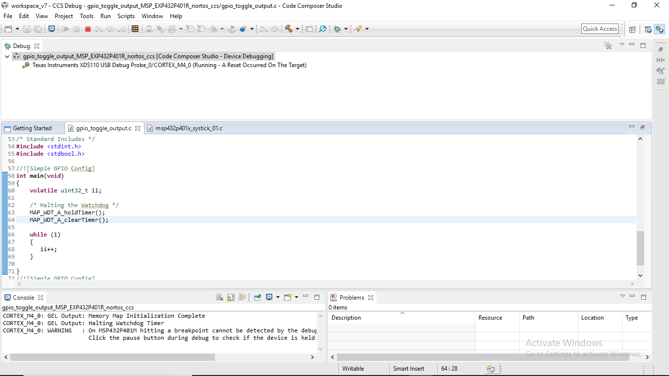
When I tested the circuit with a basic code of making one pin high on CCS the micro-controller is getting reset again and again.

I have attached the schematics of the micro-controller below.

I also tried to pull up and pull down the respective pins on the JTAG as given in the datasheet but to no avail.

Any help would be appreciated.

Thank you in Advance.

Viswanath.

  • What are you using to program the device?
    Can you take a basic example and confirm it is not the firmware? dev.ti.com/.../

    Regards,
    Chris
  • Hey Chris.

    I am using XDS110 Debug probe to program the device.

    And I am using a program from the MSP432 SDK which just toggles a pin high and low.

    Are you asking me to write a basic program and run that rather than use one from the SDK?

    Viswanath.

  • Did you disable the WDT at the beginning of your code?
  • Viswanath,
    No. I am trying to understand what software you are using to see if that might be the cause of the issue. Thank you for confirming with the example.

    I cannot see any issues from the schematic. How is Vcc applied? Please be sure that the 3.3V is applied correctly and that this is applied before interfacing the jtag or any of the IO. It is possible to 'back drive' the Vcc through the esd structure causing indeterminate behavior and possible destruction.

    Chris
  • /* DriverLib Includes */
    #include <ti/devices/msp432p4xx/driverlib/driverlib.h>
    
    /* Standard Includes */
    #include <stdint.h>
    #include <stdbool.h>
    
    int main(void)
    {
        volatile uint32_t ii;
    
        /* Halting the Watchdog */
        MAP_WDT_A_holdTimer();
    
    
        while (1)
        {
           ii++;
    
        }
    }
    
    Given above is the code which I am using to test the microcontroller.

    And as an answer to your question of how I am supplying the Vcc, I am using a regualted power supply to supply the power to the microcontroller. The power is given at the Vcc tag as shown in the schematic.

    Please ask me anything else you want to know.

    Thank you for your replies,

    Viswanath

  • /* DriverLib Includes */
    #include <ti/devices/msp432p4xx/driverlib/driverlib.h>

    /* Standard Includes */
    #include <stdint.h>
    #include <stdbool.h>

    int main(void)
    {
    volatile uint32_t ii;

    /* Halting the Watchdog */
    MAP_WDT_A_holdTimer();


    while (1)
    {
    ii++;

    }
    }

    Given above is the code which I am using to test the microcontroller. As you can see I have disabled the WDT in the starting.
  • Hi Mr. Viswanath,

    For isolation purposes, insert this after the "ii++".
    And let us see if this will reset again.

    MAP_WDT_A_clearTimer();

    Best Regards,
    Leo
  • Leo,

    Sorry for the late reply. I was on a family vacation and could not check up on the answer.

    I did try adding MAP_WDT_A_clearTimer() within the while loop as adding it after the while loop will not work.

    But it is showing the same error.

  • Hi Mr. Viswanath,

    try this other code to debug.

    I can enter and debug this code without timeout or reset so far.

    This is just a default project from MSPWare.

    Otherwise, try to change the USB Cable.

    Best Regards,

    Leo

  • I noticed your cmd file is ending with R instead of M. I have same problem which the MCU was in the loop of reset after the program uploads. Try not to use the example program made from DriveLib to have the correct link files.

    best,

    Lawrence

  • I have changed the target configuration file to MSP432P401M and then run the program will that be a problem?
  • Hi Mr. Lawrence/Mr. Viswanath,

    The only difference with the "M" and "R" is just the flash memory size.

    More likely, the memory map are still the same.

    The problem is why the custom circuit is resetting on it's own.

    It can be watchdog or a stray noise hitting the $RESET$ due to poor power supply.

    Try loading a simple counting program and we see if that resets to zero.

    Try this on Energia to narrow down the confusion, if this will exhibit the same behavior in different compiler.

    You don't need to set anything as long as it is MSP432P401X Launchpad in Energia.

    The program I will upload will work on Energia 0101E0017 Version and importable in CCS as an "Import Energia Project".

    Testing.zip

    Best Regards,

    Leo

**Attention** This is a public forum