Other Parts Discussed in Thread: MSP430FR6989
Tool/software: Code Composer Studio
I have the following code:
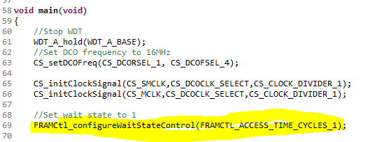
    // Setup to use internal DCO at 16 MHz
    CS_setDCOFreq(CS_DCORSEL_1, CS_DCOFSEL_4);
    //Set ACLK=DCO
    CS_initClockSignal(CS_ACLK,CS_VLOCLK_SELECT,CS_CLOCK_DIVIDER_1);
    //Set SMCLK = DCO with frequency divider of 1 for peripherals
    //(16 MHz is a good rate for UART baud rate generation)
    CS_initClockSignal(CS_SMCLK,CS_DCOCLK_SELECT,CS_CLOCK_DIVIDER_1);
    //Set MCLK = DCO with frequency divider of 1 for main CPU
    CS_initClockSignal(CS_MCLK,CS_DCOCLK_SELECT,CS_CLOCK_DIVIDER_1);
When I run these lines, the system resets continuously and I see the HFXTOFFG bit is set. However if I make this change:
    // Setup to use internal DCO at 16 MHz
    CS_setDCOFreq(CS_DCORSEL_1, CS_DCOFSEL_4);
    //Set ACLK=DCO
    CS_initClockSignal(CS_ACLK,CS_VLOCLK_SELECT,CS_CLOCK_DIVIDER_1);
    //Set MCLK = DCO with frequency divider of 1 for main CPU
    CS_initClockSignal(CS_MCLK,CS_DCOCLK_SELECT,CS_CLOCK_DIVIDER_1);
    //Set SMCLK = DCO with frequency divider of 1 for peripherals
    //(16 MHz is a good rate for UART baud rate generation)
    CS_initClockSignal(CS_SMCLK,CS_DCOCLK_SELECT,CS_CLOCK_DIVIDER_1);
Everything works fine! Also if I configure all clocks at the same time that is fine as well. Also if I drop to 8 MHz that's fine as well. It's only the combination of 16 MHz and initalizing SMCLK *before* MCLK that causes the processor to continuously reset.