This thread has been locked.

If you have a related question, please click the "Ask a related question" button in the top right corner. The newly created question will be automatically linked to this question.

MSP430F6775: MCU lockup issue when power off -> on and Vcore > DVCC shown..

Part Number: MSP430F6775

Hello Champs, 

One of my customer is developing msp430 application using F6775.

Recently they shwon the lockup issue at the power off-> on test.
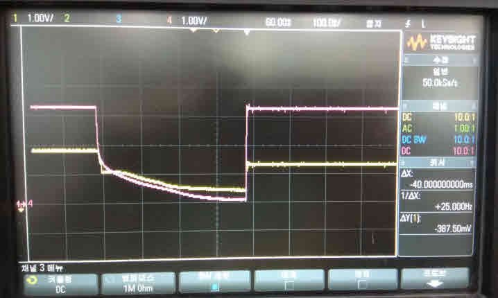
When decreasing voltage level at the power off state, their system shows the Vcore is higher than DVCC as shown below image.

<Red color : DVCC, Yellow color : Vcore, 1V/div>

If they power on when Vcore > DVCC and DVCC > 1.4V, MCU does not work properly.
Do you know any reason for that?

Note that, if they change C_Vcore from 470nF to 22nF, then it can't be Vcore > DVCC condition, then it work as normal reset.

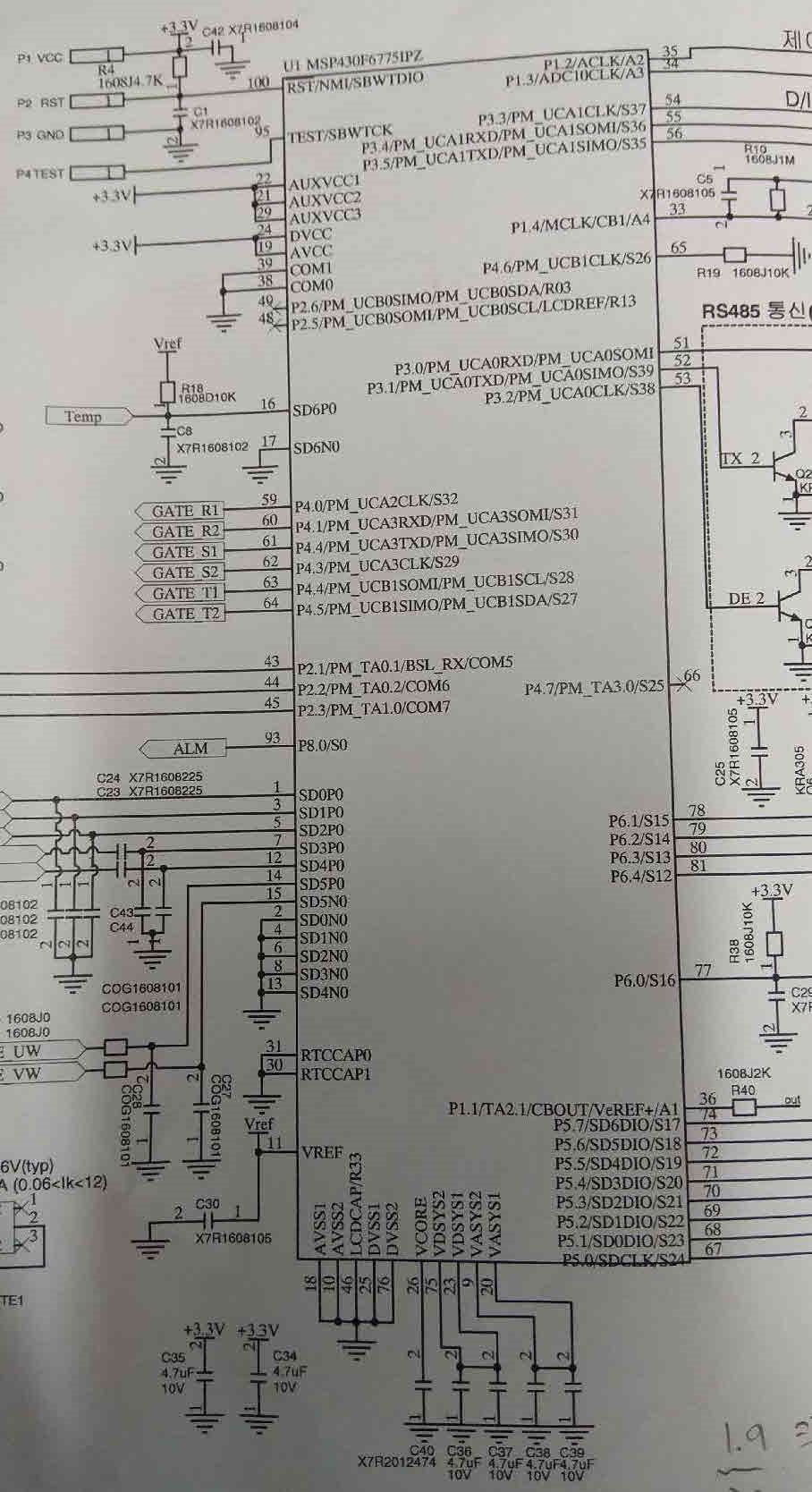
Please  see the schematic for your reference too.

Best Regards,
Ernest

  • Hello Ernest,

    While they may be meeting the minimum CDVCC / CVCORE recommended ration of > 10, I strongly suspect that there's something on the 3.3V line that's discharging the decoupling caps (and hence VCC) to a voltage below VCORE, which would make the effective ratio less than 10. The purpose of recommending this ratio is to ensure the issue you're observing never happens. When you're reducing the CVCORE to 22nF and the issue disappears, you're actually increasing the CDVCC / CVCORE ratio by reducing the denominator. I would keep CVCORE at 470nF and increase the decoupling capacitance on CDVCC.

    Regards,

    James

    MSP Customer Applications
  • It sounds (at least to me) that you are trying to solve the outcome but not the cause.
    Are you inducing a short period brown-out at the VCC? I'm not sure how you could have DVCC < VCore if the capacitor is fully discharged (changing the VCore cap to 22nF is just speeding the discharge rate). Could you have a power path through one of your signal inputs? (remember the ESD diodes).
  • Hi James, 

    They use C_DVCC as 2x4.7uF as schematic drawn. And they use SMPS and it has bigger output CAP tank.

    As you can see above picture, the curve of Vcore is staying 1V for a while and decay slowly than DVCC.
    But I can't figure out why it happen?

    In case of 22nF at the test, Vcore decayed faster and no staying at 1V was shown.

    Regards, 
    Ernest

  • One more question.
    If they do not change clock speed (they just set it up in the initialization to 25MHz) and their system only use in the Active mode,
    then is it possible to use C_Vcore as lower than datasheet(470nF)?

    Regards,
    Ernest
  • Hello Mike,
    It was not a normal test but they powered off(DVCC=Vcore=0V) and added +0.3~+0.4V at the Vcore and then powered up again.
    That case, MCU didn't wake up.
    So, that means if DVCC<Vcore case at the power on state(Also Vcore have certain points of voltage level(ie 0.5V) ), then MCU would not wake up.

    Regards,
    Ernest Cho
  • Ernest,

    I think the solution in your case is in designing a protection circuit that insures Vcore is always less than DVCC at power-on by insuring the capacitor is discharged initially. You could approach this in different ways.

**Attention** This is a public forum