This thread has been locked.

If you have a related question, please click the "Ask a related question" button in the top right corner. The newly created question will be automatically linked to this question.

MSP430G2231: MSP430 and Zero Crossing Detector

Part Number: MSP430G2231
Other Parts Discussed in Thread: CC2530, , MSP430FR2311, MSP430FR2000, MSP430G2211, MSP430G2452, MSP430G2553

HI Guys,

I´m starting to work with MSP430 and I´m really impressed with this wonderful micro controller. I already have some experience with 8051 and Texas CC2530/31.

I would like to make a synchronism between trigger wave and sine wave using Zero Crossing Detector for use it in a PWM circuit to dimmer loads over 110/220V 60 Hz.

I didn't work with Zero Crossing Detector (ZCD) before, and I would like to understanding how the best way to implement it in a MSP430.

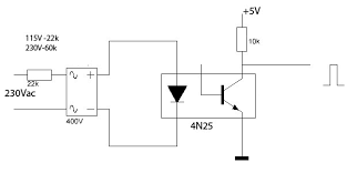
I´m using a ZCD through 4n25 optocupler like that:

I believe that I need to use:

an INTERRUPT to make a delay via timer and after it staring trigger wave on TRIAC.

Somebody can share a part of code or an AN to help me how to make it using INT or another procedure?

You can see bellow my dimmer code, using P1.3 and P1.3 pins:

#include <msp430g2231.h>

int main(void) {
WDTCTL = WDTPW + WDTHOLD;

P1DIR |= BIT2; 
P1REN |= BIT3; 
P1OUT |= BIT3;
P1SEL |= BIT2;
TA0CCR0 = 1000; 
TA0CCTL1 = OUTMOD_7;
TA0CCR1 = 0; 
TA0CTL = TASSEL_2 + MC_1;

while(1)
{
if ((P1IN & BIT3) != BIT3) {
__delay_cycles(200000);
TA0CCR1 = TA0CCR1 + 100; 
if (TA0CCR1 > 1000) { TA0CCR1 = 0; }
}
}
return 0;
}

Best Regards,

Alex

  • Hi Alex,

    Thanks for your post. You seem to be on the right track wanting to use an interrupt and timer. I see that you're using a while() loop and delay function which isn't optimal. Have you checked out our code examples in the TI Resource Explorer inside CCS for the MSP430G2231? There are several examples that showcase edge detection interrupts (like 'msp430g2xx1_P1_04.c') that you could carefully combine with one of the many timer example for your application.

    Also, make sure the voltage source that pulls up the optocoupler doesn't exceed the max input voltage to the G2231 pins.

    I'm glad that you're impressed with the MSP430G2231! Thanks for that feedback. I do want to make you aware of our newer FRAM devices like the MSP430FR2000 and MSP430FR2311. Last year we worked on an effort around 25 basic microcontroller functions with a short summary and code example. You can find them at the product folder below. Take a look at our comprehensive eBook as well.

    MSP430™ Value Line Sensing Function Code Examples

    Enhance simple analog and digital functions for $0.25 (eBook)

    Regards,

    James

    MSP Customer Applications

  • Hi James, I´m really impressed with MSP430 and the rich technical material available. Thanks a lot!

    I explore extensively TI material, to study, and I found at Air conditioner Indoor Unit a subsystem module that has a Zero Crossing Detector in a Motor Driver. As you can see PIC bellow:

    But I cant find a specific code, in Air Conditioner Indoor Unit Reference Design, with the Zero Crossing Detector code to study. Would you can help me to find a .c file that has the ZCD code part?

    www.ti.com/.../ductless_aircon_indoor_system

  • Hi Guys, I'm working on configuring my device to implement a ZCD.

    I already understood how to configure comparator_A and interrupt, but at this moment I have a basic doubt: How to configure in the MSP430G2211 with 16Mhz clock. 

    I saw in the datasheet on DCO settings frequency (15, 3) that represent 15,25 MHz and I didn't find available lib that has 16MHZ frequency, as we have for 1 MHz ( BCSCTL1 = CALBC1_1MHZ);

    - Is possible to reach 16MHz in the MSP430G2211?

    - some body can help with a code example, how can I configure it using BCSCTL1 and DCOCTL special registers?

    Best Regards,

    Alex

  • Do you have an external clock reference of some sort?

    If you have a 32kHz crystal on your board, you can use example msp430g2xx1_dco_flashcal.c to make your own CALDCO_16MHZ. If the reference is some other speed, you can adapt the principle.

    In a pinch, you can put SMCLK out through P1.4 to a scope, and adjust DCOCTL/BCSCTL1 with the debugger. (A bit of a pain, but you only have to do it once.)

    Are you required to use the G2211? The G2553 has 4x calibrated DCO values, including 16MHz.
  • Hi Bruce, thanks a lot!

    I already install a external 32KHz crystal, and got success to adjust 16MHz frequency. 

    Right now I still try to building my ZCD signal to include in my Dimmer.

    Tks!

    Alex

  • HI Bruce, how are you.

    I still working in my dimmer device, I already have success to:

    > setup clock (16MHz),

    > To building a ZCD circuit, using a LVTT (3,3V)

    > To building a PWM mechanism to trigger TRIAC

    But I working define a comparator_a for prepare a delay stage necessary for start a sincronysm between sin wave and PWM square wave. 

    But I have a problem to with comparator_A, I defined: external signal (P1.1) CARSEL, internal reference as 0,5VCC CAREF_2 and interrupt.CAIE. I using on P1.1 (P2CA4)  to tests, +VCC or GND and always the interrupt is reached (P1.0 LED toggled).

    Can you help to fix it?

    #include <msp430g2452.h>
    
    
    void main(void)
    {
    // Comaparator A settings - Set P1.0 if P1.1 > 0.5*Vcc
    WDTCTL = WDTPW +WDTHOLD; // Stop WDT
    CACTL1 = CAON +CARSEL +CAREF_2; // CAON = Enable comp , CAREF_2 = 0.5*Vcc, CARSEL1 => CAREF_2= -comp, on
    CACTL2 = P2CA4; // P1.1/CA1 = +comp
    CACTL2 |= CAF; // enable output filter
    P1DIR |= 0x01; // P1.0 output, necessary to define P1OUT
    // setup interrupts
    CACTL1 |= CAIE; // Setup interrupt for Comparator
    _BIS_SR(LPM3_bits + GIE); // Enter LPM3, interrupts enabled
    }
    
    // Comp_A interrupt service routine -- toggles LED
    #pragma vector=COMPARATORA_VECTOR
    __interrupt void Comp_A_ISR (void)
    {
    //CACTL1 ^= CAIES; // Toggles interrupt edge borda de subida ou descida.
    //CACTL1 |= CAIES; // Set up for falling (descendente) edge
    CACTL1 &= ~CAIES; // Set up for rising (ascendente) edge
    CACTL1 &= ~CAIFG; // Clear Interrupt flag
    //__delay_cycles(200000);
    P1OUT ^= 0x01; // Toggle P1.0
    }
  • Hello Alex,

    Will your input signal always be digital (VCC or GND) or analog? I'm assuming it's an analog input signal since you're using the comparator. Is the input signal the sinusoidal signal? You mentioned that you've got your ZCD working, so I'm just wondering if you couldn't use that implementation to synchronize the PWM signal and don't need the comparator. If you could provide some more background information or a high-level diagram, it'd be helpful.

    Regards,

    James
  • Hi James, thanks a lot for your assistance.

    I using digital input signal (5v or 0v) to test before my comparator A code, and after it working I planing to connect in the same PIN my ZCD output PIN,  But as I said I didn´t have a success!

    My ZCD circuit, It is similar that what I included in the first post here, but i made some adjust to work with 3,3V.

    I have planning to use follow algorithm to synchronize PWM Signal w/ sine wave form signal:

     > timer is set up but disabled

    > Zero crossing detected on pin

    > timer starts counting from zero

    > comparator set to "delay to on" value

    > counter reaches comparator value

    > comparator turns on TRIAC gate

    ...etc....
    
    If you have another way to synchronize PWM signal w/ sine wave form signal, without use Comparator A, please would you can share it w/ me?

    BR,
    Alex

  • Hello Alex,

    Revisiting your ZCD circuit, you'll have a digital output signal (PWM) with basically a 50% duty cycle (since half the sine wave is positive and the other half is negative assuming no DC offset) and variable pulse width (based on the AC period). I don't understand what you mean by "synchronizing the PWM to sine wave". There will be propagation delay introduced by the ZCD and how fast the edges of the PWM are detected by the MSP430, but it's consistent - meaning that the effective difference between the transitions shouldn't be affected by the propagation delay (it's there at the beginning and end of the pulse so it subtracts out). If you're asking how to measure the PWM on/off times (should be nearly the same as mentioned earlier) and relate that to the frequency/zero-crossings, it should be easy to accomplish using the timer module in Capture Mode (described here in the user's guide). I don't think you need the comparator module at all.

    Regards,

    James

  • Hi James, thanks a lot for your assistance. 

    I got success, as you advise me, to implement ZCD detection using only Interrupts (Port P1 Vector) and a specific electronic circuit. I working right now to adjust the clock and delay to the TRIAC gets turned off inside of the period of ½ wave.

    But right now it is my problem, I using MSP430G2452 and SMCLK clock method to ran MSP430 with 16Mhz. But I have some inconsistency when setting it together timer A used also to generate PWM wave signal. As you can see bellow the SMCLK mode uses the same registers (used to form PWM wave) TA0CTL and others.

    I need to change my MSP430G2452 to other MSP430 that has DCO inside with 16Mhz,l like MSP430G2553, or I can change capture mode and related registers to another channels like TA0CCTL2?

     // clock settings to form PWM wave
    
    TA0CCR0 = 1000; //The timer counts up to this.
    TA0CCTL1 = OUTMOD_7;
    TA0CCR1 = 0; //The PWM period, which is 0 uS.
    TA0CTL = TASSEL_2 + MC_1;
    
    /* Configure the clock module - MCLK = 1MHz */
    
    for (i = 0; i < 0xfffe; i++); // Delay for XTAL stabilization
    j = 0; // Reset pointer
    
    Set_DCO(DELTA_16MHZ); // Set DCO and obtain constants
    CAL_DATA[j++] = DCOCTL;
    CAL_DATA[j++] = BCSCTL1;
    
    Flash_ptrA = (char *)0x10C0; // Point to beginning of seg A
    FCTL2 = FWKEY + FSSEL0 + FN1; // MCLK/3 for Flash Timing Generator
    FCTL1 = FWKEY + ERASE; // Set Erase bit
    FCTL3 = FWKEY + LOCKA; // Clear LOCK & LOCKA bits
    *Flash_ptrA = 0x00; // Dummy write to erase Flash seg A
    FCTL1 = FWKEY + WRT; // Set WRT bit for write operation
    Flash_ptrA = (char *)0x10F8; // Point to beginning of cal consts
    for (j = 0; j < 8; j++)
    *Flash_ptrA++ = CAL_DATA[j]; // re-flash DCO calibration data
    FCTL1 = FWKEY; // Clear WRT bit
    FCTL3 = FWKEY + LOCKA + LOCK; // Set LOCK & LOCKA bit
    
    void Set_DCO(unsigned int Delta) // Set DCO to selected frequency
    {
    unsigned int Compare, Oldcapture = 0;
    
    BCSCTL1 |= DIVA_3; // ACLK = LFXT1CLK/8
    TACCTL0 = CM_1 + CCIS_1 + CAP; // CAP, ACLK
    TACTL = TASSEL_2 + MC_2 + TACLR; // SMCLK, cont-mode, clear
    
    while (1)
    {
    while (!(CCIFG & TACCTL0)); // Wait until capture occured
    TACCTL0 &= ~CCIFG; // Capture occured, clear flag
    Compare = TACCR0; // Get current captured SMCLK
    Compare = Compare - Oldcapture; // SMCLK difference
    Oldcapture = TACCR0; // Save current captured SMCLK
    
    if (Delta == Compare)
    break; // If equal, leave "while(1)"
    else if (Delta < Compare)
    {
    DCOCTL--; // DCO is too fast, slow it down
    if (DCOCTL == 0xFF) // Did DCO roll under?
    if (BCSCTL1 & 0x0f)
    BCSCTL1--; // Select lower RSEL
    }
    else
    {
    DCOCTL++; // DCO is too slow, speed it up
    if (DCOCTL == 0x00) // Did DCO roll over?
    if ((BCSCTL1 & 0x0f) != 0x0f)
    BCSCTL1++; // Sel higher RSEL
    }
    }
    TACCTL0 = 0; // Stop TACCR0
    TACTL = 0; // Stop Timer_A
    BCSCTL1 &= ~DIVA_3; // ACLK = LFXT1CLK
    }
  • alexander argollo said:
    I got success, as you advise me, to implement ZCD detection using only Interrupts (Port P1 Vector) and a specific electronic circuit. I working right now to adjust the clock and delay to the TRIAC gets turned off inside of the period of ½ wave.

    Great! Looking at your code, I would not adjust your DCO frequency on the fly. Instead, I would highly recommend fixing the DCO frequency and using a timer to adjust how long the TRIAC gets turned on/off inside the input period from the ZCD. This approach should be much easier and more stable.

    I'm happy to see you've got the port interrupts working to detect the ZCD detection - nice work! Now, let's assume that you want the output signal to the TRIAC to equal exactly half the ZCD period. Using your port interrupts, you could start by configuring the port interrupt to fire on rising edge. Then, when this happens, turn on the TRIAC. In your code immediately after this, you'd reconfigure the port interrupts to fire on falling edge. Then, when that interrupt fires, you'd turn off the TRIAC.

    Assuming you'd like the pulse-width to be less than half the input ZCD period, then you'd want to use a timer. After configuring the port interrupt to fire on rising interrupts from the ZCD input, start the timer when the interrupt fires and turn on the TRIAC. Then, when the timer interrupt fires after a certain delay, turn off the TRIAC output. Then, start over waiting for the next rising edge input.

    Does this make sense? Maybe I'm missing something. See the figure below illustrating what I've described. Again, I would recommend using a fixed DCO frequency.

    alexander argollo said:
    I need to change my MSP430G2452 to other MSP430 that has DCO inside with 16Mhz,l like MSP430G2553, or I can change capture mode and related registers to another channels like TA0CCTL2?

    If you're at a point in your design where you can change your MCU, I'd highly recommend switching from G2xx to our newer FRAM devices. Specifically, the similar MSP430FR2311, which is also 16MHz and has two Timer modules. If this device isn't the best for your application, there's a nice comparison table in Table 1 in the Migrating From the MSP430F2xx and MSP430G2xx Families to the MSP430FR4xx and MSP430FR2xx Family app note.

    Fundamentally, your approach won't change but there will be small changes described in this app note. As discussed in Section 3.1, some FRAM advantages include that it's inherently non-volatile memory (so it retains its content even during a power loss), doesn't require an erase before a write, and has far greater write endurance.

    Regards,

    James

  • Hi James, thanks a lot again for your assistance!!!

    Your wrote a beautiful technical words for me!!!

    Would you take a doubt?
    My actually MCU G2452 is not capable to fix DCO frequency in 16Mhz, I need to calibrate it using a DCOCTL register. I´m right?

    In positive case, to reduce a time to market and keep my actually launchpad, the G2553 MCU I can fix DCO without calibration method?

    BR,
    Alex
  • Hello Alex,

    I didn't understand what your previously-shared code was doing to the DCO, but I guess it was calibrating the DCO manually rather than using the DCOCTL register. By "fixed frequency", I mean that you can configure the DCO to run at a fixed frequency after start-up. You can use the MSP430G2553 and it's capable of 16MHZ DCO frequency. I may not understand what you're doing, but if it works without oscillator faults, then it should be fine.

    Regards,

    James
  • As I read this code, every time your program starts it re-computes the DCO constants and stores them in flash.

    I don't recommend doing this every time your program starts. The constants reflect manufacturing variations, and will not change measurably from one run to the next. Doing it this way will wear out the flash prematurely (and unnecessarily).

    Rather, you should do it once and remove the code. Then, at startup, copy the constants from flash to DCOCTL/BCSCTL1-- the way you would use the TI CAL values.
  • HI Guys, I´ll close this post. I have success to understanding a ZCD method!

    I´ll open a new if necessary to explore better about clock and frequency division method for use in PWM wave.

    Thank you all for helping me.

    BR,

    Alex

**Attention** This is a public forum