This thread has been locked.

If you have a related question, please click the "Ask a related question" button in the top right corner. The newly created question will be automatically linked to this question.

CCS/MSP430F67621: eUSCI SPI slave select (STE) stops after first transfer from master

Part Number: MSP430F67621
Other Parts Discussed in Thread: MSP430WARE

Tool/software: Code Composer Studio

I'm working on a project with an MSP430F67621A, in which I need to send data from two MSP430s to a Linux-based host. The three devices are connected over SPI, with a chip select line from the Linux host to each MSP430. The Linux host is the SPI master, and the MSP430s are slaves.

I am seeing a strange issue, whereby if I have the MSP430 eUSCI module configure in 3-pin SPI slave mode everything seems to be OK, but when I try to use 4-pin mode the MSP430 only responds to the master on the very first occasion - every time after that, the slave does not respond. (Note that although I do have two MSP430s to talk to, this example is running on just one of them, with the second being disabled).

It seems to not matter how many bytes I read in the one transfer from the master, I always get data the first time and then get zeroes on subsequent transfers. I've mapped the STE pin to P2.7.

I've set up a basic Code Composer Studio project that demonstrates the problem, this is the main.c file:

#include <stdio.h>
#include <msp430.h> 

#include <stdint.h>

uint8_t send_bytes[] = \
{
    0xAA, 0xBB, 0xCC, 0xDD, 0xEE, 0xFF, 0x11, 0x01,
    0xAA, 0xBB, 0xCC, 0xDD, 0xEE, 0xFF, 0x11, 0x02,
    0xAA, 0xBB, 0xCC, 0xDD, 0xEE, 0xFF, 0x11, 0x03,
    0xAA, 0xBB, 0xCC, 0xDD, 0xEE, 0xFF, 0x11, 0x04,
    0xAA, 0xBB, 0xCC, 0xDD, 0xEE, 0xFF, 0x11, 0x05,
    0xAA, 0xBB, 0xCC, 0xDD, 0xEE, 0xFF, 0x11, 0x06,
    0xAA, 0xBB, 0xCC, 0xDD, 0xEE, 0xFF, 0x11, 0x07,
    0xAA, 0xBB, 0xCC, 0xDD, 0xEE, 0xFF, 0x11, 0x08,
    0xAA, 0xBB, 0xCC, 0xDD, 0xEE, 0xFF, 0x11, 0x09,
    0xAA, 0xBB, 0xCC, 0xDD, 0xEE, 0xFF, 0x11, 0x0A,
    0xAA, 0xBB, 0xCC, 0xDD, 0xEE, 0xFF, 0x11, 0x0B,
    0xAA, 0xBB, 0xCC, 0xDD, 0xEE, 0xFF, 0x11, 0x0C,
    0xAA, 0xBB, 0xCC, 0xDD, 0xEE, 0xFF, 0x11, 0x0D,
    0xAA, 0xBB, 0xCC, 0xDD, 0xEE, 0xFF, 0x11, 0x0E,
    0xAA, 0xBB, 0xCC, 0xDD, 0xEE, 0xFF, 0x11, 0x0F
};

const uint8_t send_len = 120;
uint8_t send_ctr = 0;


int main(void)
{
    WDTCTL = WDTPW | WDTHOLD;   // stop watchdog timer

    // Enable global interrupt
    __bis_SR_register(GIE);


	// Configure SPI pins to secondary function mode
    P1SEL |= BIT4 | BIT5;   // P1.4 + P1.5 (UCA1SOMI, UCA1SIMO)
    P2SEL |= BIT4;          // P2.4 (UCA1CLK)

    // Configure SPI 'STE' pin
    PMAPPWD = PMAPPW;       // Enable Write-access to modify port mapping registers
    P2SEL |= BIT7;          // Set P2.7 as secondary function mode
    P2MAP7 = PM_UCA1STE;    // Map to UCA1STE function

    // Put USCI state machine into reset, so that options can be changed
    UCA1CTLW0 = UCSWRST;

    /*
     * UCA1CTLW0: USCI_A1 Control Register
     *  Bit fields mean the following:
     *      UCCKPH: Clock phase select
     *      UCCKPL: Clock polarity select
     *      UCMSB:  MSB first select
     *      UC7BIT: Character length
     *      UCMST:  Master mode select
     *      UCMODEx: USCI mode
     *      UCSYNC: Synchronous mode enable
     */
    UCA1CTLW0 =
            UCCKPH   |  // 1b = Data is captured on the first UCLK edge and changed on the following edge
            //UCCKPL  | // 0b = The inactive state is low
            UCMSB    |  // 1b = MSB first
            //UC7BIT  | // 0b = 8-bit data
            //UCMST   | // 0b = Slave mode
            UCMODE_2 |  // 10b = 4-pin SPI with UCxSTE active low: Slave enabled when UCxSTE = 0
            UCMODE_0 |  // 00b = 3-pin SPI
            UCSYNC;     // 1b = Synchronous mode

    /*
     * UCA1BR0: USCI_A1 Bit Rate Control Register 0
     * UCA1BR1: USCI_A1 Bit Rate Control Register 1
     *   Bit clock prescaler bytes. The 16-bit value of
     *   (UCA1BR0 + UCA1BR1 × 256) forms the prescaler
     *   value UCBR1.
     */
    UCA1BR0 = 0x02;
    UCA1BR1 = 0;

    // Take USCI state machine out of reset, starting it with the given options
    UCA1CTLW0 &= ~UCSWRST;

    /*
     * UCA1IE: USCI_A1 Interrupt Enable Register
     *   UCTXIE: Transmit interrupt enable
     *   UCRXIE: Receive interrupt enable
     */
    UCA1IE |= UCRXIE;   // Enable the RX interrupt
//    UCA1IE |= UCTXIE;   // Enable the TX interrupt
}


//// USCI_A1 interrupt vector service routine.
#if defined(__TI_COMPILER_VERSION__)
#pragma vector=USCI_A1_VECTOR
__interrupt
#elif defined(__GNUC__)
__attribute__((interrupt(USCI_A1_VECTOR)))
#endif
void USCI_A1_ISR (void)
{
    switch (__even_in_range(UCA1IV,2)){
        //Vector 2 - RXIFG
        case 2:
            // Wait for USCI_A1 TX buffer to be ready
            while (!(UCA1IFG & UCTXIFG));

            // Send over SPI
            UCA1TXBUF = send_bytes[send_ctr];

            send_ctr++;
            if(send_ctr > send_len){
                send_ctr = 0;
            }
            break;
        default: break;
    }
}

EDIT: Updated array and length in example

Is there something I need to do to re-enable the eUSCI module after it has been triggered as a slave by the STE pin?

  • Hi Sean,

    can you please capture scope plots of your communication with all relevant signals (SPICLK, SIMO, SOMI, STE) in case it works and in case you see an error?
    In your case you are going to send not only one byte, but multiple. Is the master still activating the slave (STE=LOW) to be able to transmit?

    Please also check the length of the array, it is 166 not 174.

    Andre
  • Thanks - I was trying to make my example code a bit neater, and tidied it up but forgot to change the length. I've fixed the example code now, the problem still happens.

    I've done a number of oscilloscope captures:

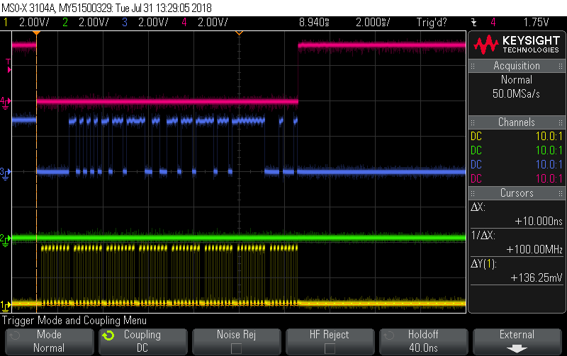
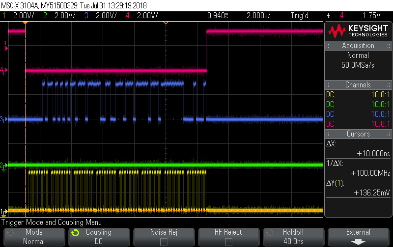
    1. Firstly, I did 8 byte transfers to the Raspberry Pi (i.e. 8× 8 bit clocks with the STE line asserted) - it seems like I can run 8-byte transfers indefinitely without any problem, the MSP430 sends the expected data for each one. (shown below)
    2. Next, I did 64 byte transfers - again, these seem to be able to run indefinitely, I can run it in a loop from the Pi and do 64 byte transfers many hundreds of times and each one has correct data.
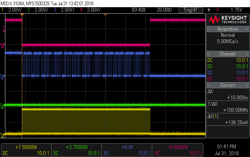
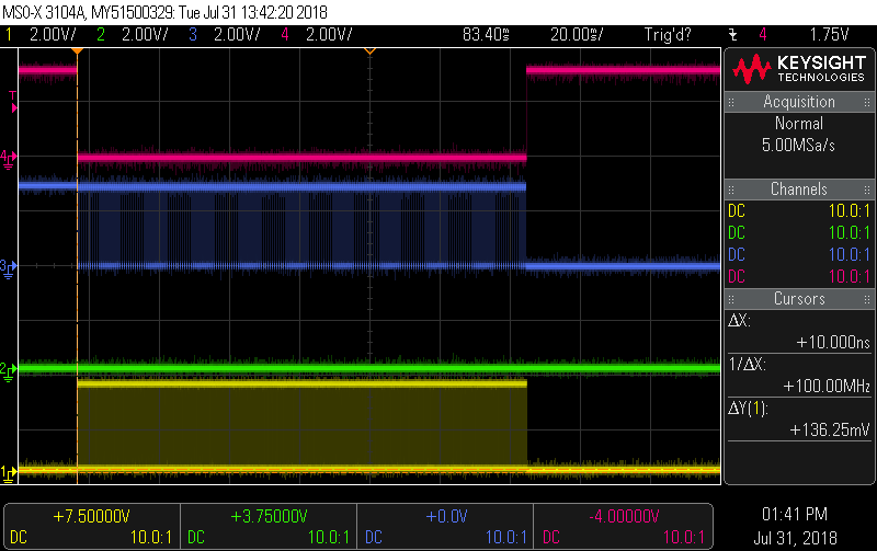
    3. Then I tried a 100 byte transfer - this is where the problem shows up. The very first 100 byte transfer works correctly, but then it seems the MSP430 gets stuck and does not continue to call the SPI ISR to add the next byte into the buffer and so the same byte is sent 100 times. (shown below)


    On the below images, the following channel mappings apply:

    • Ch 1 - Yellow: Clock
    • Ch 2 - Green: MOSI
    • Ch 3 - Blue: MISO
    • Ch 4 - Red: Chip Select (STE)

    1st 8-byte transfer:

    2nd 8-byte transfer:

    200th 8-byte transfer:


    1st 100-byte transfer:

    Note that it is hard to see in the image, but the data on MISO does change as expected.

    2nd 100-byte transfer:

    Note that the data on MISO is stuck, i.e. it's the same byte over and over again.


    When I ran the 100-byte transfer in a loop, I noticed that every so often, about 1 in 5-10 times, it would return valid data - but other times it was "stuck" at the same output.

    Is there inherently some upper limit on the number of bytes that can be sent in a single SPI transfer with the eUSCI module? It seems I can transfer as many 64-byte chunks as I like, but 100 bytes breaks the eUSCI or some other part of the MSP430 code.

  • Hi Sean,

    did you have a look at the Erratasheet, your issue could be related to the USCI50 bug.

    Besides I suggest for you to have a look at the Solutions to Common eUSCI and USCI Serial Communication Issues on MSP430 MCUs Application Report.

    A third way to tackle this issue could also be to look at the code examples we provide within MSP430Ware which should come with CCS. You can use the Ti Resource Explorer inside CCS and browse to your part. We provide SPI code examples which could also help you to find a way around your issue.

    Please let me know if you took any of those steps.

    Thanks and best regards,

    Britta

  • USCI50 does sound similar, although I'm using the MSP430 in slave mode rather than master mode.

    After some experimenting, I found that rather than doing a single 200-byte transfer I was able to instead do several 64-byte transfers. Smaller transfers also worked, but more than about 64 bytes caused problems. My MSP430 code was written such that it tracked how many bytes it had sent, and did not reset itself when the STE pin was asserted (instead the master sends a reset code if required). Then the master-side Python code simply reassembled the separate transfers.

    I didn't exactly figure out why this was the case, but for my issue it is an acceptable workaround to do several shorter transfers instead of one large transfer.
  • Hi Sean,

    you've marked this as solved as yur workaround is fine for you.
    Are you interested in further looking into what caused the issue or are you happy to move on, in that case I'd just close this thread,

    Best regards,
    Britta
  • Thanks Britta, I'm happy with the workaround, and I hope that if anyone else comes across a similar issue that this post might be helpful to them as well.
  • Glad to hear that. I'm sure this can be helpful to others, too!

    Thanks, Britta

**Attention** This is a public forum