This thread has been locked.

If you have a related question, please click the "Ask a related question" button in the top right corner. The newly created question will be automatically linked to this question.

CCS/MSP430F5359: Triggering ADC12 sampling on MSP430F5359

Part Number: MSP430F5359

Tool/software: Code Composer Studio

I am using MSP430F5359 with the MSP-TS430PZ100C development tool within CCS and am using the ADC12 module with MSP driver library. 

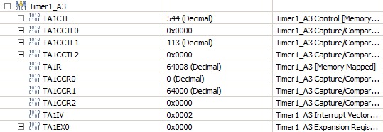
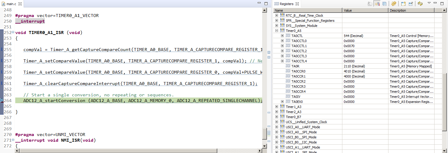
I would like to trigger the ADC12 sampling every 4ms using TimerA and grab 32 samples within that period. 

Below is what I have achieved so far and wanted some guidance to drive this further. 

#include "driverlib.h"
#define ADCpin GPIO_PORT_P6,GPIO_PIN0   // port 6 pin 0

//---prototypes
void setupADC(void);


//---globals
volatile uint16_t data;

//---main
void main(void)
{
    // Stop watch dog timer
    WDT_A_hold(WDT_A_BASE);

    // ADC setup
    setupADC();

    while(1)
    {
          // Start a single conversion, no repeating or sequences.
          ADC12_A_startConversion (ADC12_A_BASE, ADC12_A_MEMORY_0, ADC12_A_SINGLECHANNEL);

          // Wait for the Interrupt Flag to assert
          while(!(ADC12_A_getInterruptStatus(ADC12_A_BASE, ADC12IFG0)));

          // Get the value
          data = ADC12_A_getResults(ADC12_A_BASE, ADC12_A_MEMORY_0);

          // Clear the Interrupt Flag and start another conversion
          ADC12_A_clearInterrupt(ADC12_A_BASE,ADC12IFG0);
    }
}

//---setup adc
void setupADC(void)
{
    // set ADC pin
    GPIO_setAsPeripheralModuleFunctionInputPin(ADCpin);

    // Initialize the ADC12_A Module
    /* Base address of ADC12_A Module
     * Use internal ADC12_A bit as sample/hold signal to start conversion
     * USE MODOSC 5MHZ Digital Oscillator as clock source
     * Use default clock divider of 1
     */
    ADC12_A_init(ADC12_A_BASE,
                 ADC12_A_SAMPLEHOLDSOURCE_SC,
                 ADC12_A_CLOCKSOURCE_ADC12OSC,
                 ADC12_A_CLOCKDIVIDER_1);


    // setup sampling timer to sample-and-hold for 32 clock cycles
    ADC12_A_setupSamplingTimer(ADC12_A_BASE,
                               ADC12_A_CYCLEHOLD_32_CYCLES,
                               ADC12_A_CYCLEHOLD_32_CYCLES,
                               ADC12_A_MULTIPLESAMPLESDISABLE);


    //Configure Memory buffer with specified Reference voltages
    /* Base address of the ADC12_A Module
     * Configure memory buffer 0
     * Map input A12 to memory buffer 0
     * Vref+ = AVCC (internal)
     * Vref- = AVSS
     * Memory buffer 0 is not the end of a sequence
     */
    ADC12_A_configureMemoryParam param = {0};
    param.memoryBufferControlIndex = ADC12_A_MEMORY_0;
    param.inputSourceSelect = ADC12_A_INPUT_A0;
    param.positiveRefVoltageSourceSelect = ADC12_A_VREFPOS_AVCC;
    param.negativeRefVoltageSourceSelect = ADC12_A_VREFNEG_AVSS;
    param.endOfSequence = ADC12_A_NOTENDOFSEQUENCE;
    ADC12_A_configureMemory(ADC12_A_BASE,&param);

    // switch on the adc12
    ADC12_A_enable(ADC12_A_BASE);

    //Enable memory buffer 0 interrupt
    ADC12_A_enableInterrupt(ADC12_A_BASE,ADC12IE0);

}

  • Hi Pulin,

    did you have a look at the code examples provided in the MSP driver library? It could be a good starting point to have a look at the different examples and use those as a guidance. Make sure to check the code examples for the MSP430F5xx device family.
    The examples will also showcase the use of low power modes and the interrupts to save power in your application.
    After reviewing the examples please let me know if you have further questions.
    Best regards,
    Britta
  • Okay, let me start by being more specific, how do I set SMCLK to be 16MHz so that when my timer A can use it derive 4ms period that I need ? I would like to use the MSP430 Driver lib to accomplish this.
  • Hi Pulin,

    the first starting point for configuring the SMCLK would be to look at the User's Guide Section 5 Unified Clock System(UCS). Please review what source you'll be using to source the SMCLK at 16 MHz. Within the MSP430 driver library we provide different  examples for UCS configuration which might help you get started, even though some adaptions will be needed as we don't have an exact example for your desired setup.

    When the clock system is setup properly you can then use the SMCLK as Timer_A clock.

    Hope this helps you to move forward.

    Best regards,

    Britta

  • Hi Britta,

    I have modified my code in following manner to achieve 16MHz for SMCLK. 

    This is what I get. I hope you can confirm below is okay.

    Now, I have started coding up for Timer A but need further guidance on its usage with ADC12 and its interrupt routine. Hope you can hint.

    #include "driverlib.h"
    
    //---#defines
    #define ADCpin GPIO_PORT_P6,GPIO_PIN0   // port 6 pin 0
    
    #define MCLK_DESIRED_FREQUENCY_IN_KHZ 16000  // MCLK Master clock (CPU) desired = 16MHz
    #define FLLREF_KHZ 32.768 //Reference frequency (Frequency lock loop)
    
    #define MCLK_FLLREF_RATIO MCLK_DESIRED_FREQUENCY_IN_KHZ/FLLREF_KHZ
    
    
    //---prototypes
    void setupADC(void);
    void setupTimer(void);
    void initClocks(void);
    
    //---globals
    
    volatile uint16_t data;  // ADC Data
    
    uint32_t mclk = 0;    //MCLK
    uint32_t smclk = 0;   //SMCLK
    uint32_t aclk = 0;    //ACLK


    //---main
    void main(void)
    {
    
        // Stop watch dog timer
        WDT_A_hold(WDT_A_BASE);
    
        //Setup clocks
        initClocks();
    
        //Timer setup
        setupTimer();
    
        //ADC setup
        setupADC();
    
        while(1)
        {
              // Start a single conversion, no repeating or sequences.
              ADC12_A_startConversion (ADC12_A_BASE, ADC12_A_MEMORY_0, ADC12_A_SINGLECHANNEL);
              // Wait for the Interrupt Flag to assert
              while(!(ADC12_A_getInterruptStatus(ADC12_A_BASE, ADC12IFG0)));
              // Get the value
              data = ADC12_A_getResults(ADC12_A_BASE, ADC12_A_MEMORY_0);
              // Clear the Interrupt Flag and start another conversion
              ADC12_A_clearInterrupt(ADC12_A_BASE,ADC12IFG0);
        }
    }
    
    //--setup timer
    void setupTimer(void)
    {
        Timer_A_initContinuousModeParam param ={0};
        param.clockSource |= TIMER_A_CLOCKSOURCE_SMCLK;
        param.clockSourceDivider |= TIMER_A_CLOCKSOURCE_DIVIDER_1;
        param.startTimer |= false;
    }


    //--setup system clock
    void initClocks(void)
    {
    
        // Set DCO FLL reference = REFO
           UCS_initClockSignal(
               UCS_FLLREF,          // reference for frequency lock loop
               UCS_REFOCLK_SELECT,  //select 32.768KHz reference oscillator
               UCS_CLOCK_DIVIDER_1
           );
    
           // Set ACLK = REFO  set Auxiliary clock
           UCS_initClockSignal(
               UCS_ACLK,
               UCS_REFOCLK_SELECT,
               UCS_CLOCK_DIVIDER_1
           );
    
           // Set Ratio and Desired MCLK Frequency and initialise DCO
           UCS_initFLLSettle(
               MCLK_DESIRED_FREQUENCY_IN_KHZ,
               MCLK_FLLREF_RATIO
           );
    
           //Verify if the Clock settings are as expected
           mclk = UCS_getMCLK();
           aclk = UCS_getACLK();
           smclk = UCS_getSMCLK();
    
    }
    
    
    //---setup adc
    void setupADC(void)
    {
    
    
        // set ADC pin
           GPIO_setAsPeripheralModuleFunctionInputPin(ADCpin);
    
        // Initialise the ADC12_A Module
        /* Base address of ADC12_A Module
         * Use internal ADC12_A bit as sample/hold signal to start conversion
         * Use ADC12OSC 5MHZ internal Digital Oscillator as clock source
         * Use default clock divider of 1
         */
        ADC12_A_init(ADC12_A_BASE,
                     ADC12_A_SAMPLEHOLDSOURCE_1 ,
                     ADC12_A_CLOCKSOURCE_ADC12OSC,
                     ADC12_A_CLOCKDIVIDER_1);
    
    
        // setup sampling timer to sample-and-hold for 64 clock cycles
        /* Base address of ADC12_A Module
         * For memory buffers 0-7 sample/hold for 64 clock cycles
         * For memory buffers 8-15 sample/hold for 64 clock cycles
         * Disable Multiple Sampling
         */
        ADC12_A_setupSamplingTimer(ADC12_A_BASE,
                                   ADC12_A_CYCLEHOLD_64_CYCLES,
                                   ADC12_A_CYCLEHOLD_64_CYCLES,
                                   ADC12_A_MULTIPLESAMPLESDISABLE);
    
    
        //Configure Memory buffer with specified Reference voltages
        /* Base address of the ADC12_A Module
         * Configure memory buffer 0
         * Map input A12 to memory buffer 0
         * Vref+ = VREF+ (internal)
         * Vref- = AVSS
         * Memory buffer 0 is not the end of a sequence
         */
        ADC12_A_configureMemoryParam param = {0};
        param.memoryBufferControlIndex |= ADC12_A_MEMORY_0;
        param.inputSourceSelect |= ADC12_A_INPUT_A0;
        param.positiveRefVoltageSourceSelect |= ADC12_A_VREFPOS_AVCC;
        param.negativeRefVoltageSourceSelect |= ADC12_A_VREFNEG_AVSS;
        param.endOfSequence |= ADC12_A_NOTENDOFSEQUENCE;
        ADC12_A_configureMemory(ADC12_A_BASE,&param);
    
        // switch on the adc12
        ADC12_A_enable(ADC12_A_BASE);
        //Enable memory buffer 0 interrupt
       // ADC12_A_clearInterrupt(ADC12_A_BASE,ADC12IE0);
        ADC12_A_enableInterrupt(ADC12_A_BASE,ADC12IE0);
    
    }


  • Hi,

    as per your current code: I'd recommend enabling the Oscillator fault interrupts. You'll find the right driverlib functions to do so in the ucs_ex1_DCO12MHz code example.
    For the Timer and interrupt configuration I'd first recommend to check the User's Guide and the driverlib example code for ADC12 and Timer. Also, check the datasheet which Timer instance can be used to trigger the ADC. The different ADC examples should already help you, especially with the interrupt setup. The User's Guide will help to understand which setting are needed for the desired behavior.

    Best regards,
    Britta
  • Hi Britta,

    If you are referring to ADC12SHSx, from the datasheet, I can see Timer A0 is linked to ADC12_A_SAMPLEHOLDSOURCE_1

    So my ADC init statements  :

       ADC12_A_init(
              ADC12_A_BASE,
              ADC12_A_SAMPLEHOLDSOURCE_1,  
              ADC12_A_CLOCKSOURCE_ADC12OSC,
              ADC12_A_CLOCKDIVIDER_1
        );

    But the code doesn't seem to work.

    #include "driverlib.h"
    
    //---#defines
    #define ADCpin GPIO_PORT_P6,GPIO_PIN0   // port 6 pin 0
    #define No_of_samples 32 // like to grab 32 samples
    #define COMPARE_VALUE 50000


    //clock related
    #define MCLK_DESIRED_FREQUENCY_IN_KHZ 16000  // MCLK Master clock (CPU) desired = 16MHz
    #define FLLREF_KHZ 32.768 //Reference frequency (FLL)
    #define MCLK_FLLREF_RATIO MCLK_DESIRED_FREQUENCY_IN_KHZ/FLLREF_KHZ  // ratio for FLL


    //---prototypes
    void setupADC(void);
    void initTimer(void);
    void initClocks(void);


    //---globals
    volatile uint16_t data[No_of_samples];  // ADC Data
    
    uint32_t mclk = 0;    //MCLK
    uint32_t smclk = 0;   //SMCLK
    uint32_t aclk = 0;    //ACLK
    uint16_t status;


    //---main
    void main(void)
    {
    
        // Stop watch dog timer
        WDT_A_hold(WDT_A_BASE);
    
        //Setup clocks
        initClocks();
    
        //Verify if the Clock settings are as expected
        mclk = UCS_getMCLK();
        aclk = UCS_getACLK();
        smclk = UCS_getSMCLK();
    
        //Timer setup
        initTimer();
    
        //ADC setup
         setupADC();
    
        // Enable global interrupt
        __bis_SR_register(GIE);
    
        __no_operation();    //for debugger
    
    }
    
    //--setup timer in continuous mode sourced by SMCLK
    void initTimer(void)
    {
        Timer_A_initContinuousModeParam param ={0};
        param.clockSource = TIMER_A_CLOCKSOURCE_SMCLK;
        param.clockSourceDivider = TIMER_A_CLOCKSOURCE_DIVIDER_1;
        param.timerInterruptEnable_TAIE = TIMER_A_TAIE_INTERRUPT_DISABLE;
        param.timerClear = TIMER_A_DO_CLEAR;
        param.startTimer = false;
        Timer_A_initContinuousMode(TIMER_A0_BASE, &param);
    
        //Initialise compare mode
       Timer_A_clearCaptureCompareInterrupt(TIMER_A1_BASE, TIMER_A_CAPTURECOMPARE_REGISTER_0);
       Timer_A_initCompareModeParam initCompParam = {0};
       initCompParam.compareRegister = TIMER_A_CAPTURECOMPARE_REGISTER_0;
       initCompParam.compareInterruptEnable = TIMER_A_CAPTURECOMPARE_INTERRUPT_ENABLE;
       initCompParam.compareOutputMode = TIMER_A_OUTPUTMODE_OUTBITVALUE;
       initCompParam.compareValue = COMPARE_VALUE;
       Timer_A_initCompareMode(TIMER_A1_BASE, &initCompParam);
    
       Timer_A_startCounter( TIMER_A1_BASE,TIMER_A_CONTINUOUS_MODE);
    
    }
    
    //--setup system clocks
    void initClocks(void)
    {
    
        // Set DCO FLL reference = REFO
           UCS_initClockSignal(
               UCS_FLLREF,          // reference for frequency lock loop
               UCS_REFOCLK_SELECT,  //select 32.768KHz reference oscillator
               UCS_CLOCK_DIVIDER_1
           );
    
           // Set ACLK = REFO  set Auxiliary clock
           UCS_initClockSignal(
               UCS_ACLK,
               UCS_REFOCLK_SELECT,
               UCS_CLOCK_DIVIDER_1
           );
    
           // Start the FLL and let it settle
           // This becomes the MCLK and SMCLK automatically
           // set desired frequency and load the ratio
           UCS_initFLLSettle(
               MCLK_DESIRED_FREQUENCY_IN_KHZ,
               MCLK_FLLREF_RATIO
           );
    
           // Enable global oscillator fault flag
           SFR_clearInterrupt(
                SFR_OSCILLATOR_FAULT_INTERRUPT
           );
           SFR_enableInterrupt(
                SFR_OSCILLATOR_FAULT_INTERRUPT
           );
    
    }
    
    //---setup adc
    void setupADC(void)
    {
    
        // set ADC pin
        GPIO_setAsPeripheralModuleFunctionInputPin(ADCpin);
    
        // Initialise the ADC12_A Module
        /* Base address of ADC12_A Module
         * Use internal ADC12_A bit as sample/hold signal to start conversion
         * Use ADC12OSC 5MHZ internal Digital Oscillator as clock source
         * Use default clock divider of 1
         */
        ADC12_A_init(
              ADC12_A_BASE,
              ADC12_A_SAMPLEHOLDSOURCE_1,
              ADC12_A_CLOCKSOURCE_ADC12OSC,
              ADC12_A_CLOCKDIVIDER_1
        );
    
        ADC12_A_enable(ADC12_A_BASE);
    
        // setup sampling timer to sample-and-hold for 64 clock cycles
        /* Base address of ADC12_A Module
         * For memory buffers 0-7 sample/hold for 64 clock cycles
         * For memory buffers 8-15 sample/hold for 64 clock cycles
         * Disable Multiple Sampling
         */
        ADC12_A_setupSamplingTimer(
              ADC12_A_BASE,
              ADC12_A_CYCLEHOLD_64_CYCLES,
              ADC12_A_CYCLEHOLD_4_CYCLES,
              ADC12_A_MULTIPLESAMPLESENABLE
        );
    
    
        //Configure Memory buffer with specified Reference voltages
        /* Base address of the ADC12_A Module
         * Configure memory buffer 0
         * Map input A12 to memory buffer 0
         * Vref+ = VREF+ (internal)
         * Vref- = AVSS
         * Memory buffer 0 is not the end of a sequence
         */
        ADC12_A_configureMemoryParam param = {0};
        param.memoryBufferControlIndex |= ADC12_A_MEMORY_0;
        param.inputSourceSelect |= ADC12_A_INPUT_A0;
        param.positiveRefVoltageSourceSelect |= ADC12_A_VREFPOS_AVCC;
        param.negativeRefVoltageSourceSelect |= ADC12_A_VREFNEG_AVSS;
        param.endOfSequence |= ADC12_A_NOTENDOFSEQUENCE;
        ADC12_A_configureMemory(ADC12_A_BASE,&param);
    
        //Enable memory buffer 0 interrupt
         ADC12_A_clearInterrupt(ADC12_A_BASE,ADC12IE0);
         ADC12_A_enableInterrupt(ADC12_A_BASE,ADC12IE0);
    
        // Start a single conversion, no repeating or sequences.
        ADC12_A_startConversion (ADC12_A_BASE, ADC12_A_MEMORY_0, ADC12_A_REPEATED_SINGLECHANNEL);
    
    
    }
    
    #pragma vector = ADC12_VECTOR
    __interrupt void ADC12_ISR(void)
    {
    
          static uint8_t index = 0;
    
        switch (__even_in_range(ADC12IV,34)){
            case  0: break;   //Vector  0:  No interrupt
            case  2: break;   //Vector  2:  ADC overflow
            case  4: break;   //Vector  4:  ADC timing overflow
            case  6:          //Vector  6:  ADC12IFG0
                //Move results
                data[index] = ADC12_A_getResults(ADC12_A_BASE, ADC12_A_MEMORY_0);
    
                //Increment results index, modulo;
                //Set Breakpoint1 here and watch results[]
                index++;
    
                if (index == 32)
                {
                    index = 0;
                }
            case  8: break;   //Vector  8:  ADC12IFG1
            case 10: break;   //Vector 10:  ADC12IFG2
            case 12: break;   //Vector 12:  ADC12IFG3
            case 14: break;   //Vector 14:  ADC12IFG4
            case 16: break;   //Vector 16:  ADC12IFG5
            case 18: break;   //Vector 18:  ADC12IFG6
            case 20: break;   //Vector 20:  ADC12IFG7
            case 22: break;   //Vector 22:  ADC12IFG8
            case 24: break;   //Vector 24:  ADC12IFG9
            case 26: break;   //Vector 26:  ADC12IFG10
            case 28: break;   //Vector 28:  ADC12IFG11
            case 30: break;   //Vector 30:  ADC12IFG12
            case 32: break;   //Vector 32:  ADC12IFG13
            case 34: break;   //Vector 34:  ADC12IFG14
            default: break;
        }
    
    }


    #pragma vector=TIMER1_A0_VECTOR
    __interrupt
    
    void TIMER1_A0_ISR (void)
    {
        uint16_t compVal = Timer_A_getCaptureCompareCount(TIMER_A1_BASE, TIMER_A_CAPTURECOMPARE_REGISTER_0) + COMPARE_VALUE;
    
        //Toggle P1.0  // the green led is on it
        GPIO_toggleOutputOnPin(
            GPIO_PORT_P1,
            GPIO_PIN0
            );
    
        //Add Offset to CCR0
        Timer_A_setCompareValue(TIMER_A1_BASE,
            TIMER_A_CAPTURECOMPARE_REGISTER_0,
            compVal
            );
    }
    
    
    #pragma vector=UNMI_VECTOR
    __interrupt void NMI_ISR(void)
    {
            do {
                    // If it still can't clear the oscillator fault flags after the timeout,
                    // trap and wait here.
                    status = UCS_clearAllOscFlagsWithTimeout(1000);
            } while (status != 0);
    }


  • > initCompParam.compareRegister = TIMER_A_CAPTURECOMPARE_REGISTER_0;
    Per data sheet Table 6-14, SHS=1 refers to TA0.1, not TA0.0. You need to use TIMER_A_CAPTURECOMPARE_REGISTER_1 (CCR1) instead. There is no SHS for TA0.0, so you can't just change that.

    There are a few references that need to be fixed for this. Also you'll need to change to
    >#pragma vector=TIMER1_A1_VECTOR
    and you'll need to explicitly clear the CCR1 interrupt in the ISR with something like:
    > Timer_A_clearCaptureCompareInterrupt(TIMER_A1_BASE, TIMER_A_CAPTURECOMPARE_REGISTER_1);
    ---------------------------
    > initCompParam.compareOutputMode = TIMER_A_OUTPUTMODE_OUTBITVALUE;
    You need to generate an actual waveform to do the trigger, which OUTBITVALUE won't. Try TIMER_A_OUTPUTMODE_SET_RESET.
  • Hi Bruce, 

    I made changes as per your suggestions but also moved ADC12_A_startConversion into the Timer ISR. Is that correct way of doing it ? 

    So, if the timer overflow frequency is 250Hz, and SMCLK is 16MHz, the 4ms is represented by 64000 as a count value for CCR1 

    Also, when  ADC12_A_SAMPLEHOLDSOURCE_1 is changed to ADC12_A_SAMPLEHOLDSOURCE_SC , it seems to behave. Otherwise it doesn't work

    ADC12_A_init(
    ADC12_A_BASE,
    ADC12_A_SAMPLEHOLDSOURCE_1,      <---- when this changed to ADC12_A_SAMPLEHOLDSOURCE_SC , it seems to behave.

    ADC12_A_CLOCKSOURCE_ADC12OSC,

    ADC12_A_CLOCKDIVIDER_1
    );


    #include "driverlib.h" //---#defines #define ADCpin GPIO_PORT_P6,GPIO_PIN0 // port 6 pin 0 #define No_of_samples 32 // like to grab 32 samples #define COMPARE_VALUE 64000 //clock related #define MCLK_DESIRED_FREQUENCY_IN_KHZ 16000 // MCLK Master clock (CPU) desired = 16MHz #define FLLREF_KHZ 32.768 //Reference frequency (FLL) #define MCLK_FLLREF_RATIO MCLK_DESIRED_FREQUENCY_IN_KHZ/FLLREF_KHZ // ratio for FLL //---prototypes void initADC(void); void initTimers(void); void initClocks(void); void initGPIO(void); //---globals volatile uint16_t data[No_of_samples]; // ADC Data volatile uint16_t comparevalue; uint32_t mclk = 0; //MCLK uint32_t smclk = 0; //SMCLK uint32_t aclk = 0; //ACLK uint16_t status; //---main void main(void) { // Stop watch dog timer WDT_A_hold(WDT_A_BASE); //Configure GPIO ports/pins initGPIO(); //Setup clocks initClocks(); //Verify if the Clock settings are as expected mclk = UCS_getMCLK(); aclk = UCS_getACLK(); smclk = UCS_getSMCLK(); //Timer setup initTimers(); //ADC setup initADC(); // Enable global interrupt __bis_SR_register(GIE); } void initGPIO(void) { // set P1.0 as output GPIO_setAsOutputPin(GPIO_PORT_P1, GPIO_PIN0); } //--setup timer in continuous mode sourced by SMCLK void initTimers(void) { Timer_A_initContinuousModeParam param ={0}; param.clockSource = TIMER_A_CLOCKSOURCE_SMCLK; param.clockSourceDivider = TIMER_A_CLOCKSOURCE_DIVIDER_1; param.timerInterruptEnable_TAIE = TIMER_A_TAIE_INTERRUPT_DISABLE; param.timerClear = TIMER_A_DO_CLEAR; param.startTimer = false; Timer_A_initContinuousMode(TIMER_A1_BASE, &param); //Initialise compare mode Timer_A_clearCaptureCompareInterrupt(TIMER_A1_BASE, TIMER_A_CAPTURECOMPARE_REGISTER_1); Timer_A_initCompareModeParam initCompParam = {0}; initCompParam.compareRegister = TIMER_A_CAPTURECOMPARE_REGISTER_1; initCompParam.compareInterruptEnable = TIMER_A_CAPTURECOMPARE_INTERRUPT_ENABLE; initCompParam.compareOutputMode = TIMER_A_OUTPUTMODE_SET_RESET; initCompParam.compareValue = COMPARE_VALUE; Timer_A_initCompareMode(TIMER_A1_BASE, &initCompParam); Timer_A_startCounter( TIMER_A1_BASE,TIMER_A_CONTINUOUS_MODE); } //--setup system clocks void initClocks(void) { // Set DCO FLL reference = REFO UCS_initClockSignal( UCS_FLLREF, // reference for frequency lock loop UCS_REFOCLK_SELECT, //select 32.768KHz reference oscillator UCS_CLOCK_DIVIDER_1 ); // Set ACLK = REFO set Auxiliary clock UCS_initClockSignal( UCS_ACLK, UCS_REFOCLK_SELECT, UCS_CLOCK_DIVIDER_1 ); // Start the FLL and let it settle // This becomes the MCLK and SMCLK automatically // set desired frequency and load the ratio UCS_initFLLSettle( MCLK_DESIRED_FREQUENCY_IN_KHZ, MCLK_FLLREF_RATIO ); // Enable global oscillator fault flag SFR_clearInterrupt( SFR_OSCILLATOR_FAULT_INTERRUPT ); SFR_enableInterrupt( SFR_OSCILLATOR_FAULT_INTERRUPT ); } //---setup adc void initADC(void) { // set ADC pin GPIO_setAsPeripheralModuleFunctionInputPin(ADCpin); // Initialise the ADC12_A Module /* Base address of ADC12_A Module * Use internal ADC12_A bit as sample/hold signal to start conversion * Use ADC12OSC 5MHZ internal Digital Oscillator as clock source * Use default clock divider of 1 */ ADC12_A_init( ADC12_A_BASE, ADC12_A_SAMPLEHOLDSOURCE_SC, ADC12_A_CLOCKSOURCE_ADC12OSC, ADC12_A_CLOCKDIVIDER_1 ); ADC12_A_enable(ADC12_A_BASE); // setup sampling timer to sample-and-hold for 64 clock cycles /* Base address of ADC12_A Module * For memory buffers 0-7 sample/hold for 64 clock cycles * For memory buffers 8-15 sample/hold for 64 clock cycles * Disable Multiple Sampling */ ADC12_A_setupSamplingTimer( ADC12_A_BASE, ADC12_A_CYCLEHOLD_64_CYCLES, ADC12_A_CYCLEHOLD_4_CYCLES, ADC12_A_MULTIPLESAMPLESENABLE ); //Configure Memory buffer with specified Reference voltages /* Base address of the ADC12_A Module * Configure memory buffer 0 * Map input A12 to memory buffer 0 * Vref+ = VREF+ (internal) * Vref- = AVSS * Memory buffer 0 is not the end of a sequence */ ADC12_A_configureMemoryParam param = {0}; param.memoryBufferControlIndex |= ADC12_A_MEMORY_0; param.inputSourceSelect |= ADC12_A_INPUT_A0; param.positiveRefVoltageSourceSelect |= ADC12_A_VREFPOS_AVCC; param.negativeRefVoltageSourceSelect |= ADC12_A_VREFNEG_AVSS; param.endOfSequence |= ADC12_A_NOTENDOFSEQUENCE; ADC12_A_configureMemory(ADC12_A_BASE,&param); //Enable memory buffer 0 interrupt ADC12_A_clearInterrupt(ADC12_A_BASE,ADC12IE0); ADC12_A_enableInterrupt(ADC12_A_BASE,ADC12IE0); // Start a single conversion, no repeating or sequences. // ADC12_A_startConversion (ADC12_A_BASE, ADC12_A_MEMORY_0, ADC12_A_REPEATED_SINGLECHANNEL); } #pragma vector = ADC12_VECTOR __interrupt void ADC12_ISR(void) { static uint8_t index = 0; switch (__even_in_range(ADC12IV,34)){ case 0: break; //Vector 0: No interrupt case 2: break; //Vector 2: ADC overflow case 4: break; //Vector 4: ADC timing overflow case 6: //Vector 6: ADC12IFG0 //Move results data[index] = ADC12_A_getResults(ADC12_A_BASE, ADC12_A_MEMORY_0); //Increment results index, modulo; //Set Breakpoint1 here and watch results[] index++; if (index == 32) { index = 0; } case 8: break; //Vector 8: ADC12IFG1 case 10: break; //Vector 10: ADC12IFG2 case 12: break; //Vector 12: ADC12IFG3 case 14: break; //Vector 14: ADC12IFG4 case 16: break; //Vector 16: ADC12IFG5 case 18: break; //Vector 18: ADC12IFG6 case 20: break; //Vector 20: ADC12IFG7 case 22: break; //Vector 22: ADC12IFG8 case 24: break; //Vector 24: ADC12IFG9 case 26: break; //Vector 26: ADC12IFG10 case 28: break; //Vector 28: ADC12IFG11 case 30: break; //Vector 30: ADC12IFG12 case 32: break; //Vector 32: ADC12IFG13 case 34: break; //Vector 34: ADC12IFG14 default: break; } } #pragma vector=TIMER1_A1_VECTOR __interrupt void TIMER1_A1_ISR (void) { comparevalue = Timer_A_getCaptureCompareCount(TIMER_A1_BASE, TIMER_A_CAPTURECOMPARE_REGISTER_1); //Toggle the green led GPIO_toggleOutputOnPin(GPIO_PORT_P1,GPIO_PIN0); // Start ADC conversion. ADC12_A_startConversion (ADC12_A_BASE, ADC12_A_MEMORY_0, ADC12_A_REPEATED_SINGLECHANNEL); Timer_A_clearCaptureCompareInterrupt(TIMER_A1_BASE, TIMER_A_CAPTURECOMPARE_REGISTER_1); } #pragma vector=UNMI_VECTOR __interrupt void NMI_ISR(void) { do { // If it still can't clear the oscillator fault flags after the timeout, // trap and wait here. status = UCS_clearAllOscFlagsWithTimeout(1000); } while (status != 0); }

  • Does "doesn't work" mean the ADC doesn't run at all, or it runs too fast? My reading of this code suggests the second.

    > ADC12_A_MULTIPLESAMPLESENABLE
    In combination with CONSEQ=2 (ADC12_A_REPEATED_SINGLECHANNEL) this will run the ADC as fast as it can run, which I think isn't the goal. I suggest you replace this with:
    > ADC12_A_REPEATED_SINGLECHANNELDISABLE // MSC=0
    This will repeat a single channel, but paced by the timer. Then I think you can put back
    > ADC12_A_SAMPLEHOLDSOURCE_1, // SHS=1
    and move the ADC12_A_startConversion call back into main.

    [Edit: The key here is that startConversion will set ENC=1, which will allow the timer to trigger the ADC. It will also set SC, but that will be ignored since SHS != 0.]

    [Edit: The diagram in User Guide (SLAU208Q) Fig. 28-9 is useful for keeping track of the interaction between CONSEQ=2, MSC, and SHS ("Trigger").]
    ------------------
    Since you're running the timer in Continuous mode, the period will be 65536 ticks (~244 Hz). The fact that you're triggering 64000 ticks into the cycle won't change the period.

    In the previous version, you were accomplishing this by moving CCR0 forward by your period each time, and doing the same thing (with CCR1) will work fine here.

    You could also switch to Up mode, use CYCLE_COUNT for the period (CCR0) and something smaller, say CYCLE_COUNT/2 for the CCR1 compare.

    The first (moving CCR1 forward) is probably the smallest change -- just adapt the line from your earlier code:
    > Timer_A_setCompareValue(TIMER_A1_BASE, TIMER_A_CAPTURECOMPARE_REGISTER_1, compVal+CYCLE_COUNT );

  • ADC12_A_REPEATED_SINGLECHANNELDISABLE doesn't exist as an option(look at adc12_a.h) so chose ADC12_A_SINGLECHANNEL (ADC12CONSEQ_0)

    Left it in continous mode and other changes per your suggestions. ADC isn't triggering as far as I can see. Are you sure that the instance of timer should be Timer1_A3 ?

    #include "driverlib.h"
    
    //---#defines
    #define ADCpin GPIO_PORT_P6,GPIO_PIN0   // port 6 pin 0
    #define No_of_samples 32 // like to grab 32 samples
    #define COMPARE_VALUE 64000
    
    
    //clock related
    #define MCLK_DESIRED_FREQUENCY_IN_KHZ 16000  // MCLK Master clock (CPU) desired = 16MHz
    #define FLLREF_KHZ 32.768 //Reference frequency (FLL)
    #define MCLK_FLLREF_RATIO MCLK_DESIRED_FREQUENCY_IN_KHZ/FLLREF_KHZ  // ratio for FLL
    
    
    //---prototypes
    void initADC(void);
    void initTimers(void);
    void initClocks(void);
    void initGPIO(void);
    
    //---globals
    volatile uint16_t data[No_of_samples];  // ADC Data
    
    uint32_t mclk = 0;    //MCLK
    uint32_t smclk = 0;   //SMCLK
    uint32_t aclk = 0;    //ACLK
    uint16_t status;
    
    
    //---main
    void main(void)
    {
    
        // Stop watch dog timer
        WDT_A_hold(WDT_A_BASE);
    
    
        //Configure GPIO ports/pins
        initGPIO();
    
        //Setup clocks
        initClocks();
    
        //Verify if the Clock settings are as expected
        mclk = UCS_getMCLK();
        aclk = UCS_getACLK();
        smclk = UCS_getSMCLK();
    
        //Timer setup
        initTimers();
    
        //ADC setup
         initADC();
    
        // Enable global interrupt
        __bis_SR_register(GIE);
    
    }
    
    
    void initGPIO(void)
    {
        // set P1.0 as output
        GPIO_setAsOutputPin(GPIO_PORT_P1, GPIO_PIN0);
    }


    //--setup timer
    void initTimers(void)
    {


        //Start timer in continuous mode sourced by SMCLK
          Timer_A_initContinuousModeParam initContParam = {0};
          initContParam.clockSource = TIMER_A_CLOCKSOURCE_SMCLK;
          initContParam.clockSourceDivider = TIMER_A_CLOCKSOURCE_DIVIDER_1;
          initContParam.timerInterruptEnable_TAIE = TIMER_A_TAIE_INTERRUPT_DISABLE;
          initContParam.timerClear = TIMER_A_DO_CLEAR;
          initContParam.startTimer = false;
          Timer_A_initContinuousMode(TIMER_A1_BASE, &initContParam);


         //Initialise compare mode
            Timer_A_clearCaptureCompareInterrupt(TIMER_A1_BASE, TIMER_A_CAPTURECOMPARE_REGISTER_1);
    
            Timer_A_initCompareModeParam initCompParam = {0};
            initCompParam.compareRegister = TIMER_A_CAPTURECOMPARE_REGISTER_1;
            initCompParam.compareInterruptEnable = TIMER_A_CAPTURECOMPARE_INTERRUPT_ENABLE;
            initCompParam.compareOutputMode = TIMER_A_OUTPUTMODE_SET_RESET;
            initCompParam.compareValue = COMPARE_VALUE;
            Timer_A_initCompareMode(TIMER_A1_BASE, &initCompParam);
    
            Timer_A_startCounter(TIMER_A1_BASE,TIMER_A_CONTINUOUS_MODE);
    
    }
    
    
    //--setup system clocks
    void initClocks(void)
    {
    
        // Set DCO FLL reference = REFO
           UCS_initClockSignal(
               UCS_FLLREF,          // reference for frequency lock loop
               UCS_REFOCLK_SELECT,  //select 32.768KHz reference oscillator
               UCS_CLOCK_DIVIDER_1
           );
    
           // Set ACLK = REFO  set Auxiliary clock
           UCS_initClockSignal(
               UCS_ACLK,
               UCS_REFOCLK_SELECT,
               UCS_CLOCK_DIVIDER_1
           );
    
           // Start the FLL and let it settle
           // This becomes the MCLK and SMCLK automatically
           // set desired frequency and load the ratio
           UCS_initFLLSettle(
               MCLK_DESIRED_FREQUENCY_IN_KHZ,
               MCLK_FLLREF_RATIO
           );
    
           // Enable global oscillator fault flag
           SFR_clearInterrupt(
                SFR_OSCILLATOR_FAULT_INTERRUPT
           );
           SFR_enableInterrupt(
                SFR_OSCILLATOR_FAULT_INTERRUPT
           );
    
    }
    
    //---setup adc
    void initADC(void)
    {
    
        // set ADC pin
        GPIO_setAsPeripheralModuleFunctionInputPin(ADCpin);
    
        // Initialise the ADC12_A Module
        /* Base address of ADC12_A Module
         * Use internal ADC12_A bit as sample/hold signal to start conversion
         * Use ADC12OSC 5MHZ internal Digital Oscillator as clock source
         * Use default clock divider of 1
         */
        ADC12_A_init(
              ADC12_A_BASE,
              ADC12_A_SAMPLEHOLDSOURCE_1,
              ADC12_A_CLOCKSOURCE_ADC12OSC,
              ADC12_A_CLOCKDIVIDER_1
        );
    
        ADC12_A_enable(ADC12_A_BASE);
    
        // setup sampling timer to sample-and-hold for 64 clock cycles
        /* Base address of ADC12_A Module
         * For memory buffers 0-7 sample/hold for 64 clock cycles
         * For memory buffers 8-15 sample/hold for 64 clock cycles
         * Disable Multiple Sampling
         */
        ADC12_A_setupSamplingTimer(
              ADC12_A_BASE,
              ADC12_A_CYCLEHOLD_32_CYCLES,
              ADC12_A_CYCLEHOLD_32_CYCLES,
              ADC12_A_MULTIPLESAMPLESDISABLE
        );
    
    
        //Configure Memory buffer with specified Reference voltages
        /* Base address of the ADC12_A Module
         * Configure memory buffer 0
         * Map input A12 to memory buffer 0
         * Vref+ = VREF+ (internal)
         * Vref- = AVSS
         * Memory buffer 0 is not the end of a sequence
         */
        ADC12_A_configureMemoryParam param = {0};
        param.memoryBufferControlIndex |= ADC12_A_MEMORY_0;
        param.inputSourceSelect |= ADC12_A_INPUT_A0;
        param.positiveRefVoltageSourceSelect |= ADC12_A_VREFPOS_AVCC;
        param.negativeRefVoltageSourceSelect |= ADC12_A_VREFNEG_AVSS;
        param.endOfSequence |= ADC12_A_NOTENDOFSEQUENCE;
        ADC12_A_configureMemory(ADC12_A_BASE,&param);
    
        //Enable memory buffer 0 interrupt
         ADC12_A_clearInterrupt(ADC12_A_BASE,ADC12IE0);
         ADC12_A_enableInterrupt(ADC12_A_BASE,ADC12IE0);
    
        // Start a single conversion, no repeating or sequences.
        ADC12_A_startConversion (ADC12_A_BASE, ADC12_A_MEMORY_0, ADC12_A_SINGLECHANNEL);
    
    
    }
    
    #pragma vector = ADC12_VECTOR
    __interrupt void ADC12_ISR(void)
    {
    
          static uint8_t index = 0;
    
        switch (__even_in_range(ADC12IV,34)){
            case  0: break;   //Vector  0:  No interrupt
            case  2: break;   //Vector  2:  ADC overflow
            case  4: break;   //Vector  4:  ADC timing overflow
            case  6:          //Vector  6:  ADC12IFG0
                //Move results
                data[index] = ADC12_A_getResults(ADC12_A_BASE, ADC12_A_MEMORY_0);
    
                //Increment results index, modulo;
                //Set Breakpoint1 here and watch results[]
                index++;
    
                if (index == 32)
                {
                    index = 0;
    
                }
            case  8: break;   //Vector  8:  ADC12IFG1
            case 10: break;   //Vector 10:  ADC12IFG2
            case 12: break;   //Vector 12:  ADC12IFG3
            case 14: break;   //Vector 14:  ADC12IFG4
            case 16: break;   //Vector 16:  ADC12IFG5
            case 18: break;   //Vector 18:  ADC12IFG6
            case 20: break;   //Vector 20:  ADC12IFG7
            case 22: break;   //Vector 22:  ADC12IFG8
            case 24: break;   //Vector 24:  ADC12IFG9
            case 26: break;   //Vector 26:  ADC12IFG10
            case 28: break;   //Vector 28:  ADC12IFG11
            case 30: break;   //Vector 30:  ADC12IFG12
            case 32: break;   //Vector 32:  ADC12IFG13
            case 34: break;   //Vector 34:  ADC12IFG14
            default: break;
        }
    
    }


    #pragma vector=TIMER1_A1_VECTOR
    __interrupt
    
    void TIMER1_A1_ISR (void)
    {
    
       uint16_t compVal = Timer_A_getCaptureCompareCount(TIMER_A1_BASE, TIMER_A_CAPTURECOMPARE_REGISTER_1) + COMPARE_VALUE;
    
       //Add Offset to CCR1
       Timer_A_setCompareValue(TIMER_A1_BASE, TIMER_A_CAPTURECOMPARE_REGISTER_1,compVal+COMPARE_VALUE);
    
    }


    #pragma vector=UNMI_VECTOR
    __interrupt void NMI_ISR(void)
    {
            do {
                    // If it still can't clear the oscillator fault flags after the timeout,
                    // trap and wait here.
                    status = UCS_clearAllOscFlagsWithTimeout(1000);
            } while (status != 0);
    }

  • > ADC12_A_REPEATED_SINGLECHANNELDISABLE
    Sorry, that was a paste error on my part. I actually looked at that 3 times before I saw the mistake. I meant to say:
    > ADC12_A_MULTIPLESAMPLESDISABLE // MSC=0
    or you could just say 0.

    I don't think you want ADC12_A_SINGLECHANNEL (CONSEQ=0) since (per User Guide (SLAU208Q) Fig. 28-7) you have to toggle ENC twice (low then high) for each conversion. With CONSEQ=2 and MSC=0 (Fig 28-9) you avoid that. The symptom would be that you get no triggers after the first one.
    -----------------------------------
    You should also add to your ISR:
    > Timer_A_clearCaptureCompareInterrupt(TIMER_A1_BASE, TIMER_A_CAPTURECOMPARE_REGISTER_1);
    The CCR0 interrupt clears by itself, but the CCR1 one doesn't.
  • Hi Bruce,

    ADC isn't getting triggered at all.  

    Following snapshots are of single stepping into the code. 

    Register view(below) after init Timers() (in main) :

    Register view (below) as it hits Timer1_A1_ISR() very first time.   

    Register view at the end of the timer ISR 

    #include "driverlib.h"
    
    //---#defines
    #define ADCpin GPIO_PORT_P6,GPIO_PIN0   // port 6 pin 0
    #define No_of_samples 32 // like to grab 32 samples
    #define COMPARE_VALUE 64000
    
    
    //clock related
    #define MCLK_DESIRED_FREQUENCY_IN_KHZ 16000  // MCLK Master clock (CPU) desired = 16MHz
    #define FLLREF_KHZ 32.768 //Reference frequency (FLL)
    #define MCLK_FLLREF_RATIO MCLK_DESIRED_FREQUENCY_IN_KHZ/FLLREF_KHZ  // ratio for FLL
    
    
    //---prototypes
    void initADC(void);
    void initTimers(void);
    void initClocks(void);
    void initGPIO(void);
    
    //---globals
    volatile uint16_t data[No_of_samples];  // ADC Data
    volatile uint16_t compVal=0;
    
    uint32_t mclk = 0;    //MCLK
    uint32_t smclk = 0;   //SMCLK
    uint32_t aclk = 0;    //ACLK
    uint16_t status;
    
    
    //---main
    void main(void)
    {
    
        // Stop watch dog timer
        WDT_A_hold(WDT_A_BASE);
    
    
        //Configure GPIO ports/pins
        initGPIO();
    
        //Setup clocks
        initClocks();
    
        //Verify if the Clock settings are as expected
        mclk = UCS_getMCLK();
        aclk = UCS_getACLK();
        smclk = UCS_getSMCLK();
    
        //Timer setup
        initTimers();
    
        //ADC setup
         initADC();
    
        // Enable global interrupt
        __bis_SR_register(GIE);
    
    }
    
    
    void initGPIO(void)
    {
        // set P1.0 as output
        GPIO_setAsOutputPin(GPIO_PORT_P1, GPIO_PIN0);
    }


    //--setup timer
    void initTimers(void)
    {


        //Start timer in continuous mode sourced by SMCLK
          Timer_A_initContinuousModeParam initContParam = {0};
          initContParam.clockSource = TIMER_A_CLOCKSOURCE_SMCLK;
          initContParam.clockSourceDivider = TIMER_A_CLOCKSOURCE_DIVIDER_1;
          initContParam.timerInterruptEnable_TAIE = TIMER_A_TAIE_INTERRUPT_DISABLE;
          initContParam.timerClear = TIMER_A_DO_CLEAR;
          initContParam.startTimer = false;
          Timer_A_initContinuousMode(TIMER_A1_BASE, &initContParam);


         //Initialise compare mode
            Timer_A_clearCaptureCompareInterrupt(TIMER_A1_BASE, TIMER_A_CAPTURECOMPARE_REGISTER_1);
    
            Timer_A_initCompareModeParam initCompParam = {0};
            initCompParam.compareRegister = TIMER_A_CAPTURECOMPARE_REGISTER_1;
            initCompParam.compareInterruptEnable = TIMER_A_CAPTURECOMPARE_INTERRUPT_ENABLE;
            initCompParam.compareOutputMode = TIMER_A_OUTPUTMODE_SET_RESET;
            initCompParam.compareValue = COMPARE_VALUE;
            Timer_A_initCompareMode(TIMER_A1_BASE, &initCompParam);
    
            Timer_A_startCounter(TIMER_A1_BASE,TIMER_A_CONTINUOUS_MODE);
    
    }
    
    
    //--setup system clocks
    void initClocks(void)
    {
    
        // Set DCO FLL reference = REFO
           UCS_initClockSignal(
               UCS_FLLREF,          // reference for frequency lock loop
               UCS_REFOCLK_SELECT,  //select 32.768KHz reference oscillator
               UCS_CLOCK_DIVIDER_1
           );
    
           // Set ACLK = REFO  set Auxiliary clock
           UCS_initClockSignal(
               UCS_ACLK,
               UCS_REFOCLK_SELECT,
               UCS_CLOCK_DIVIDER_1
           );
    
           // Start the FLL and let it settle
           // This becomes the MCLK and SMCLK automatically
           // set desired frequency and load the ratio
           UCS_initFLLSettle(
               MCLK_DESIRED_FREQUENCY_IN_KHZ,
               MCLK_FLLREF_RATIO
           );
    
           // Enable global oscillator fault flag
           SFR_clearInterrupt(
                SFR_OSCILLATOR_FAULT_INTERRUPT
           );
           SFR_enableInterrupt(
                SFR_OSCILLATOR_FAULT_INTERRUPT
           );
    
    }
    
    //---setup adc
    void initADC(void)
    {
    
        // set ADC pin
        GPIO_setAsPeripheralModuleFunctionInputPin(ADCpin);
    
        // Initialise the ADC12_A Module
        /* Base address of ADC12_A Module
         * Use internal ADC12_A bit as sample/hold signal to start conversion
         * Use ADC12OSC 5MHZ internal Digital Oscillator as clock source
         * Use default clock divider of 1
         */
        ADC12_A_init(
              ADC12_A_BASE,
              ADC12_A_SAMPLEHOLDSOURCE_1,
              ADC12_A_CLOCKSOURCE_ADC12OSC,
              ADC12_A_CLOCKDIVIDER_1
        );
    
        ADC12_A_enable(ADC12_A_BASE);
    
        // setup sampling timer to sample-and-hold for 64 clock cycles
        /* Base address of ADC12_A Module
         * For memory buffers 0-7 sample/hold for 64 clock cycles
         * For memory buffers 8-15 sample/hold for 64 clock cycles
         * Disable Multiple Sampling
         */
        ADC12_A_setupSamplingTimer(
              ADC12_A_BASE,
              ADC12_A_CYCLEHOLD_32_CYCLES,
              ADC12_A_CYCLEHOLD_32_CYCLES,
              ADC12_A_MULTIPLESAMPLESDISABLE
        );
    
    
        //Configure Memory buffer with specified Reference voltages
        /* Base address of the ADC12_A Module
         * Configure memory buffer 0
         * Map input A12 to memory buffer 0
         * Vref+ = VREF+ (internal)
         * Vref- = AVSS
         * Memory buffer 0 is not the end of a sequence
         */
        ADC12_A_configureMemoryParam param = {0};
        param.memoryBufferControlIndex |= ADC12_A_MEMORY_0;
        param.inputSourceSelect |= ADC12_A_INPUT_A0;
        param.positiveRefVoltageSourceSelect |= ADC12_A_VREFPOS_AVCC;
        param.negativeRefVoltageSourceSelect |= ADC12_A_VREFNEG_AVSS;
        param.endOfSequence |= ADC12_A_NOTENDOFSEQUENCE;
        ADC12_A_configureMemory(ADC12_A_BASE,&param);
    
        //Enable memory buffer 0 interrupt
         ADC12_A_clearInterrupt(ADC12_A_BASE,ADC12IE0);
         ADC12_A_enableInterrupt(ADC12_A_BASE,ADC12IE0);
    
        // Start a single conversion, no repeating or sequences.
        ADC12_A_startConversion (ADC12_A_BASE, ADC12_A_MEMORY_0, ADC12_A_REPEATED_SINGLECHANNEL);  // conseq = 2
    
    
    }
    
    #pragma vector = ADC12_VECTOR
    __interrupt void ADC12_ISR(void)
    {
    
          static uint8_t index = 0;
    
        switch (__even_in_range(ADC12IV,34)){
            case  0: break;   //Vector  0:  No interrupt
            case  2: break;   //Vector  2:  ADC overflow
            case  4: break;   //Vector  4:  ADC timing overflow
            case  6:          //Vector  6:  ADC12IFG0
                //Move results
                data[index] = ADC12_A_getResults(ADC12_A_BASE, ADC12_A_MEMORY_0);
    
                //Increment results index, modulo;
                //Set Breakpoint1 here and watch results[]
                index++;
    
                if (index == 32)
                {
                    index = 0;
    
                }
            case  8: break;   //Vector  8:  ADC12IFG1
            case 10: break;   //Vector 10:  ADC12IFG2
            case 12: break;   //Vector 12:  ADC12IFG3
            case 14: break;   //Vector 14:  ADC12IFG4
            case 16: break;   //Vector 16:  ADC12IFG5
            case 18: break;   //Vector 18:  ADC12IFG6
            case 20: break;   //Vector 20:  ADC12IFG7
            case 22: break;   //Vector 22:  ADC12IFG8
            case 24: break;   //Vector 24:  ADC12IFG9
            case 26: break;   //Vector 26:  ADC12IFG10
            case 28: break;   //Vector 28:  ADC12IFG11
            case 30: break;   //Vector 30:  ADC12IFG12
            case 32: break;   //Vector 32:  ADC12IFG13
            case 34: break;   //Vector 34:  ADC12IFG14
            default: break;
        }
    
    }


    #pragma vector=TIMER1_A1_VECTOR
    __interrupt
    
    void TIMER1_A1_ISR (void)
    {
    
       compVal = Timer_A_getCaptureCompareCount(TIMER_A1_BASE, TIMER_A_CAPTURECOMPARE_REGISTER_1) + COMPARE_VALUE;
    
       //Add Offset to CCR1
       Timer_A_setCompareValue(TIMER_A1_BASE, TIMER_A_CAPTURECOMPARE_REGISTER_1,compVal+COMPARE_VALUE);
    
       Timer_A_clearCaptureCompareInterrupt(TIMER_A1_BASE, TIMER_A_CAPTURECOMPARE_REGISTER_1);
    
    }


    #pragma vector=UNMI_VECTOR
    __interrupt void NMI_ISR(void)
    {
            do {
                    // If it still can't clear the oscillator fault flags after the timeout,
                    // trap and wait here.
                    status = UCS_clearAllOscFlagsWithTimeout(1000);
            } while (status != 0);
    }


  • > ADC12_A_SAMPLEHOLDSOURCE_1,
    > Timer_A_startCounter(TIMER_A1_BASE,TIMER_A_CONTINUOUS_MODE);
    Per data sheet (SLAS700D) Table 6-14, SHS=1 is TA0.1, not TA1.1. I don't see any SHS setting associated with TA1.

    You should be using TIMER_A0 (and its CCR1) throughout. I guess I missed when you made that change.

    Unsolicited:
    > compVal = Timer_A_getCaptureCompareCount(TIMER_A1_BASE, TIMER_A_CAPTURECOMPARE_REGISTER_1) + COMPARE_VALUE;
    > Timer_A_setCompareValue(TIMER_A1_BASE, TIMER_A_CAPTURECOMPARE_REGISTER_1,compVal+COMPARE_VALUE);
    This is double-incrementing. This isn't your bug now, but it will be eventually.
  • Hi Bruce,

    I did mention that to Britta in my earlier posts(table showing TA0 connections).

    Anyways, I have reverted back to using TIMER_A0 and the ADC seems to be triggering.

    Every 4ms interval, I want the ADC ISR to gather 32 samples. How can I achieve this ?  

    I understand that in continuous mode, the overflow will occur after 65536 ticks. So, if i set CCR1 to 64000 (4ms) thats when the ADC ISR will fire.

    Is my understanding of this correct ?

    Regards

    Pulin

    #include "driverlib.h"
    
    //---#defines
    #define ADCpin GPIO_PORT_P6,GPIO_PIN0   // port 6 pin 0
    #define No_of_samples 32 // like to grab 32 samples
    #define COMPARE_VALUE 64000
    
    
    //clock related
    #define MCLK_DESIRED_FREQUENCY_IN_KHZ 16000  // MCLK Master clock (CPU) desired = 16MHz
    #define FLLREF_KHZ 32.768 //Reference frequency (FLL)
    #define MCLK_FLLREF_RATIO MCLK_DESIRED_FREQUENCY_IN_KHZ/FLLREF_KHZ  // ratio for FLL
    
    
    //---prototypes
    void initADC(void);
    void initTimers(void);
    void initClocks(void);
    void initGPIO(void);
    
    //---globals
    volatile uint16_t data[No_of_samples];  // ADC Data
    volatile uint16_t compVal=0;
    
    uint32_t mclk = 0;    //MCLK
    uint32_t smclk = 0;   //SMCLK
    uint32_t aclk = 0;    //ACLK
    uint16_t status;
    
    
    //---main
    void main(void)
    {
    
        // Stop watch dog timer
        WDT_A_hold(WDT_A_BASE);
    
    
        //Configure GPIO ports/pins
        initGPIO();
    
        //Setup clocks
        initClocks();
    
        //Verify if the Clock settings are as expected
        mclk = UCS_getMCLK();
        aclk = UCS_getACLK();
        smclk = UCS_getSMCLK();
    
        //Timer setup
        initTimers();
    
        //ADC setup
         initADC();
    
        // Enable global interrupt
        __bis_SR_register(GIE);
    
        while(1)
        {
    
        }
    
    }
    
    
    void initGPIO(void)
    {
        // set P1.0 as output
        GPIO_setAsOutputPin(GPIO_PORT_P1, GPIO_PIN0);
    }


    //--setup timer
    void initTimers(void)
    {
    
        //Start timer in continuous mode sourced by SMCLK
          Timer_A_initContinuousModeParam initContParam = {0};
          initContParam.clockSource = TIMER_A_CLOCKSOURCE_SMCLK;
          initContParam.clockSourceDivider = TIMER_A_CLOCKSOURCE_DIVIDER_1;
          initContParam.timerInterruptEnable_TAIE = TIMER_A_TAIE_INTERRUPT_DISABLE;
          initContParam.timerClear = TIMER_A_DO_CLEAR;
          initContParam.startTimer = false;
          Timer_A_initContinuousMode(TIMER_A0_BASE, &initContParam);
    
         //Initialise compare mode
           Timer_A_clearCaptureCompareInterrupt(TIMER_A0_BASE, TIMER_A_CAPTURECOMPARE_REGISTER_1);
    
           Timer_A_initCompareModeParam initCompParam = {0};
           initCompParam.compareRegister = TIMER_A_CAPTURECOMPARE_REGISTER_1;
           initCompParam.compareInterruptEnable = TIMER_A_CAPTURECOMPARE_INTERRUPT_ENABLE;
           initCompParam.compareOutputMode = TIMER_A_OUTPUTMODE_SET_RESET;
           initCompParam.compareValue = COMPARE_VALUE;
           Timer_A_initCompareMode(TIMER_A0_BASE, &initCompParam);
           Timer_A_startCounter(TIMER_A0_BASE,TIMER_A_CONTINUOUS_MODE);
    }
    
    
    //--setup system clocks
    void initClocks(void)
    {
    
        // Set DCO FLL reference = REFO
           UCS_initClockSignal(
               UCS_FLLREF,          // reference for frequency lock loop
               UCS_REFOCLK_SELECT,  //select 32.768KHz reference oscillator
               UCS_CLOCK_DIVIDER_1
           );
    
           // Set ACLK = REFO  set Auxiliary clock
           UCS_initClockSignal(
               UCS_ACLK,
               UCS_REFOCLK_SELECT,
               UCS_CLOCK_DIVIDER_1
           );
    
           // Start the FLL and let it settle
           // This becomes the MCLK and SMCLK automatically
           // set desired frequency and load the ratio
           UCS_initFLLSettle(
               MCLK_DESIRED_FREQUENCY_IN_KHZ,
               MCLK_FLLREF_RATIO
           );
    
           // Enable global oscillator fault flag
           SFR_clearInterrupt(
                SFR_OSCILLATOR_FAULT_INTERRUPT
           );
           SFR_enableInterrupt(
                SFR_OSCILLATOR_FAULT_INTERRUPT
           );
    
    }
    
    //---setup adc
    void initADC(void)
    {
    
        // set ADC pin
        GPIO_setAsPeripheralModuleFunctionInputPin(ADCpin);
    
        // Initialise the ADC12_A Module
        /* Base address of ADC12_A Module
         * Use internal ADC12_A bit as sample/hold signal to start conversion
         * Use ADC12OSC 5MHZ internal Digital Oscillator as clock source
         * Use default clock divider of 1
         */
        ADC12_A_init(
              ADC12_A_BASE,
              ADC12_A_SAMPLEHOLDSOURCE_1,
              ADC12_A_CLOCKSOURCE_ADC12OSC,
              ADC12_A_CLOCKDIVIDER_1
        );
    
        ADC12_A_enable(ADC12_A_BASE);
    
        // setup sampling timer to sample-and-hold for 64 clock cycles
        /* Base address of ADC12_A Module
         * For memory buffers 0-7 sample/hold for 64 clock cycles
         * For memory buffers 8-15 sample/hold for 64 clock cycles
         * Disable Multiple Sampling
         */
        ADC12_A_setupSamplingTimer(
              ADC12_A_BASE,
              ADC12_A_CYCLEHOLD_32_CYCLES,
              ADC12_A_CYCLEHOLD_32_CYCLES,
              ADC12_A_MULTIPLESAMPLESDISABLE
        );
    
    
        //Configure Memory buffer with specified Reference voltages
        /* Base address of the ADC12_A Module
         * Configure memory buffer 0
         * Map input A12 to memory buffer 0
         * Vref+ = VREF+ (internal)
         * Vref- = AVSS
         * Memory buffer 0 is not the end of a sequence
         */
        ADC12_A_configureMemoryParam param = {0};
        param.memoryBufferControlIndex |= ADC12_A_MEMORY_0;
        param.inputSourceSelect |= ADC12_A_INPUT_A0;
        param.positiveRefVoltageSourceSelect |= ADC12_A_VREFPOS_AVCC;
        param.negativeRefVoltageSourceSelect |= ADC12_A_VREFNEG_AVSS;
        param.endOfSequence |= ADC12_A_NOTENDOFSEQUENCE;
        ADC12_A_configureMemory(ADC12_A_BASE,&param);
    
        //Enable memory buffer 0 interrupt
         ADC12_A_clearInterrupt(ADC12_A_BASE,ADC12IE0);
         ADC12_A_enableInterrupt(ADC12_A_BASE,ADC12IE0);
    
        // Start a single conversion, no repeating or sequences.
        ADC12_A_startConversion (ADC12_A_BASE, ADC12_A_MEMORY_0, ADC12_A_REPEATED_SINGLECHANNEL);  // conseq = 2
    
    
    }
    
    #pragma vector = ADC12_VECTOR
    __interrupt void ADC12_ISR(void)
    {
    
          static uint8_t index = 0;
    
        switch (__even_in_range(ADC12IV,34)){
            case  0: break;   //Vector  0:  No interrupt
            case  2: break;   //Vector  2:  ADC overflow
            case  4: break;   //Vector  4:  ADC timing overflow
            case  6:          //Vector  6:  ADC12IFG0
                //Move results
                data[index] = ADC12_A_getResults(ADC12_A_BASE, ADC12_A_MEMORY_0);
    
                //Increment results index, modulo;
                //Set Breakpoint1 here and watch results[]
                index++;
    
                if (index == 32)
                {
                    index = 0;
    
                }
            case  8: break;   //Vector  8:  ADC12IFG1
            case 10: break;   //Vector 10:  ADC12IFG2
            case 12: break;   //Vector 12:  ADC12IFG3
            case 14: break;   //Vector 14:  ADC12IFG4
            case 16: break;   //Vector 16:  ADC12IFG5
            case 18: break;   //Vector 18:  ADC12IFG6
            case 20: break;   //Vector 20:  ADC12IFG7
            case 22: break;   //Vector 22:  ADC12IFG8
            case 24: break;   //Vector 24:  ADC12IFG9
            case 26: break;   //Vector 26:  ADC12IFG10
            case 28: break;   //Vector 28:  ADC12IFG11
            case 30: break;   //Vector 30:  ADC12IFG12
            case 32: break;   //Vector 32:  ADC12IFG13
            case 34: break;   //Vector 34:  ADC12IFG14
            default: break;
        }
    
    }


    #pragma vector=TIMER0_A1_VECTOR
    __interrupt
    
    void TIMER0_A1_ISR (void)
    {
    
       compVal = Timer_A_getCaptureCompareCount(TIMER_A0_BASE, TIMER_A_CAPTURECOMPARE_REGISTER_1) + COMPARE_VALUE;
    
       //Add Offset to CCR1
       Timer_A_setCompareValue(TIMER_A0_BASE, TIMER_A_CAPTURECOMPARE_REGISTER_1,COMPARE_VALUE);
    
    
       Timer_A_clearCaptureCompareInterrupt(TIMER_A0_BASE, TIMER_A_CAPTURECOMPARE_REGISTER_1);
    
    }


    #pragma vector=UNMI_VECTOR
    __interrupt void NMI_ISR(void)
    {
            do {
                    // If it still can't clear the oscillator fault flags after the timeout,
                    // trap and wait here.
                    status = UCS_clearAllOscFlagsWithTimeout(1000);
            } while (status != 0);
    }


  • > Every 4ms interval, I want the ADC ISR to gather 32 samples. How can I achieve this ?
    Do you mean a burst (fast-as-possible) of 32 every 4ms "tick", or just 32 samples evenly spaced over each 4ms? For the latter, I think you can just divide COMPARE_VALUE by 32 (=2000). The former would require a bit of thought.
    ----------------
    Unsolicited:
    It occurred to me that since LCM(64000,65536)=8192000 /64000=128, every 128th computed CCR1 value will be 0 (==CCR0) and you won't get a pulse (zero-length). This is the kind of thing which will sneak up on you a few months from now. The simplest fix is probably to move CCR0 forward in tandem with CCR1, just a few ticks later:

    > Timer_A_setCompareValue(TIMER_A0_BASE, TIMER_A_CAPTURECOMPARE_REGISTER_1, compVal); // New CCR1
    #define PULSE_WIDTH 10 // Arbitrary: small, >0
    > Timer_A_setCompareValue(TIMER_A0_BASE, TIMER_A_CAPTURECOMPARE_REGISTER_0, compVal+PULSE_WIDTH); // New CCR0
  • Hi Bruce, I was referring to PWM signal (through set-reset mode) with 4ms on and 4ms off time. During the 4ms on time, the ADC ISR will take 32 evenly spaced samples.
  • The short answer is no. The ADC trigger is an edge, not a (high) level. If you want 32 samples in 4 ms -- 1 per 125usec -- the timer needs to generate an edge every 125usec, changing its frequency from 250Hz to 8kHz.

    The ADC also doesn't really provide a mechanism for turning it on/off (e.g. ENC=0) automatically, i.e. without software intervention.

    One simple (if slightly distasteful) approach is to throw out every other batch of 32 samples.
  • 
    

    Hi Bruce,

    I found an example below and was wondering if it is similar to what I want. That is enabling ADC through timer.


    /* --COPYRIGHT--,BSD_EX
    
     * Copyright (c) 2012, Texas Instruments Incorporated
    
     * All rights reserved.
    
     *
    
     * Redistribution and use in source and binary forms, with or without
    
     * modification, are permitted provided that the following conditions
    
     * are met:
    
     *
    
     * *  Redistributions of source code must retain the above copyright
    
     *    notice, this list of conditions and the following disclaimer.
    
     *
    
     * *  Redistributions in binary form must reproduce the above copyright
    
     *    notice, this list of conditions and the following disclaimer in the
    
     *    documentation and/or other materials provided with the distribution.
    
     *
    
     * *  Neither the name of Texas Instruments Incorporated nor the names of
    
     *    its contributors may be used to endorse or promote products derived
    
     *    from this software without specific prior written permission.
    
     *
    
     * THIS SOFTWARE IS PROVIDED BY THE COPYRIGHT HOLDERS AND CONTRIBUTORS "AS IS"
    
     * AND ANY EXPRESS OR IMPLIED WARRANTIES, INCLUDING, BUT NOT LIMITED TO,
    
     * THE IMPLIED WARRANTIES OF MERCHANTABILITY AND FITNESS FOR A PARTICULAR
    
     * PURPOSE ARE DISCLAIMED. IN NO EVENT SHALL THE COPYRIGHT OWNER OR
    
     * CONTRIBUTORS BE LIABLE FOR ANY DIRECT, INDIRECT, INCIDENTAL, SPECIAL,
    
     * EXEMPLARY, OR CONSEQUENTIAL DAMAGES (INCLUDING, BUT NOT LIMITED TO,
    
     * PROCUREMENT OF SUBSTITUTE GOODS OR SERVICES; LOSS OF USE, DATA, OR PROFITS;
    
     * OR BUSINESS INTERRUPTION) HOWEVER CAUSED AND ON ANY THEORY OF LIABILITY,
    
     * WHETHER IN CONTRACT, STRICT LIABILITY, OR TORT (INCLUDING NEGLIGENCE OR
    
     * OTHERWISE) ARISING IN ANY WAY OUT OF THE USE OF THIS SOFTWARE,
    
     * EVEN IF ADVISED OF THE POSSIBILITY OF SUCH DAMAGE.
    
     *
    
     *******************************************************************************
    
     * 
    
     *                       MSP430 CODE EXAMPLE DISCLAIMER
    
     *
    
     * MSP430 code examples are self-contained low-level programs that typically
    
     * demonstrate a single peripheral function or device feature in a highly
    
     * concise manner. For this the code may rely on the device's power-on default
    
     * register values and settings such as the clock configuration and care must
    
     * be taken when combining code from several examples to avoid potential side
    
     * effects. Also see www.ti.com/grace for a GUI- and www.ti.com/msp430ware
    
     * for an API functional library-approach to peripheral configuration.
    
     *
    
     * --/COPYRIGHT--*/
    
    //******************************************************************************
    
    //  MSP430G2x33/G2x53 Demo - ADC10, Sample A7, 1.5V, TA1 Trig, Ultra-Low Pwr
    
    //
    
    //  Description: A7 is sampled 1024/second (32xACLK)with reference to 1.5V. All
    
    //  activity is interrupt driven with proper usage of MSP430 low-power modes,
    
    //  ADC10 and Vref demonstrated. Timer_A with both TA1/TA0 used in upmode to
    
    //  drive ADC10 conversion (continuous mode can also be used). Inside
    
    //  of TA0_ISR software will enable ADC10 and internal reference and
    
    //  allow > 30us delay for Vref to stabilize prior to sample start. Sample
    
    //  start is automatically triggered by TA1 every 32 ACLK cycles. ADC10_ISR
    
    //  will disable ADC10 and Vref and compare ADC10 conversion code. Internal
    
    //  oscillator times sample (16x) and conversion (13x). If A7 > 0.2Vcc,
    
    //  P1.0 is set, else reset. Normal Mode is LPM3.
    
    //  //* An external watch crystal on XIN XOUT is required for ACLK *//
    
    //
    
    //                    +-----(0.9766us)---------\\------------------>+
    
    //    TA0_ISR        TA1      ADC10_ISR             TA0_ISR        TA1
    
    //  -----+------------+------------+-----------\\------+------------+----->
    
    //   Enable ADC    Trigger ADC  Disable ADC
    
    //   and Vref                   Compare
    
    //       +-( >30us--->+
    
    //
    
    //
    
    //               MSP430G2x33/G2x53
    
    //            -----------------
    
    //        /|\|              XIN|-
    
    //         | |                 | 32kHz
    
    //         --|RST          XOUT|-
    
    //           |                 |
    
    //       >---|P1.7/A7     P1.0 |--> LED
    
    //
    
    //  D. Dang
    
    //  Texas Instruments Inc.
    
    //  December 2010
    
    //   Built with CCS Version 4.2.0 and IAR Embedded Workbench Version: 5.10
    
    //******************************************************************************
    
    #include <msp430.h>


    int main(void)
    
    {
    
      WDTCTL = WDTPW + WDTHOLD;                 // Stop WDT


      ADC10CTL1 = INCH_7 + SHS_1;               // P1.7, TA1 trigger sample start
    
      ADC10AE0 = 0x80;                          // P1.7 ADC10 option select
    
      P1DIR |= 0x01;                            // Set P1.0 to output direction
    
      TACCTL0 = CCIE;                           // Enable interrupt
    
      TACCR0 = 32-1;                            // PWM Period
    
      TACCTL1 = OUTMOD_3;                       // TACCR1 set/reset
    
      TACCR1 = 2;                               // TACCR1 PWM Duty Cycle
    
      TACTL = TASSEL_1 + MC_1;                  // ACLK, up mode
    
      __bis_SR_register(LPM3_bits + GIE);       // Enter LPM3, enable interrupts
    
    }


    // ADC10 interrupt service routine
    
    #pragma vector=ADC10_VECTOR
    
    __interrupt void ADC10_ISR(void)
    
    {
    
      ADC10CTL0 &= ~ENC;                        // ADC10 disabled
    
      ADC10CTL0 = 0;                            // ADC10, Vref disabled completely
    
      if (ADC10MEM < 0x88)                      // ADC10MEM = A7 > 0.2V?
    
        P1OUT &= ~0x01;                         // Clear P1.0 LED off
    
      else
    
        P1OUT |= 0x01;                          // Set P1.0 LED on
    
    }


    // Timer A0 interrupt service routine
    
    #pragma vector=TIMER0_A0_VECTOR
    
    __interrupt void Timer_A(void)
    
    {
    
      ADC10CTL0 = SREF_1 + ADC10SHT_2 + REFON + ADC10ON + ADC10IE;
    
      ADC10CTL0 |= ENC;                         // ADC10 enable set
    
    }


  • Yes, this is the kind of "software intervention" I referred to.

    1) The ADC ISR counts to 32, then sets ENC=0.
    2) The timer ISR counts to (2*32), then sets ENC=1.

    You don't want the timer setting ENC=0 since the ADC may/may not be actively converting at that moment, causing the ADC ISR some ambiguity. [Ref User Guide (SLAU208Q) sec. 28.2.7.6]

    As long as you're careful to keep the counters in sync, I think this should work fine.

    (Go through the sequence yourself, to make sure I'm not off-by-1 somewhere.)
  • Hi Bruce,

    I found this table on the forums describing interaction of SHP, SHSx and MSC. What setting is relevant to what I am trying to do ?

    I understand that since I am using pulse sample mode, SHP = 0. 

  • You can see what your settings are by pausing in the debugger and looking in the Registers window. Last I saw you were using:
    CONSEQ=2: ADC12_A_REPEATED_SINGLECHANNEL
    SHP=1: ADC12_A_setupSamplingTimer(
    SHS=1: ADC12_A_SAMPLEHOLDSOURCE_1,
    MSC=0: ADC12_A_MULTIPLESAMPLESDISABLE
    I suppose you could use SHP=0 with a suitable change to your timer setup, but I don't see what it would gain you.
    -----------------------------------
    How did your method from yesterday work out? Do your measurements look the way you expected?
  • Hi Bruce,

    Going back to our conversation yesterday, I am still confused with Timer and its ISR.

    If you want 32 samples in 4 ms -- 1 per 125usec -- the timer needs to generate an edge every 125usec, changing its frequency from 250Hz to 8kHz.

    >>> I set COMPARE_VALUE to 2000 (16MHz/8KHz)  so my TA0CCR1 is set to 2000.   What needs to be set to 4000 then ? TACCR0 ?

    My code below is broken:

    #include "driverlib.h"
    
    //---#defines
    #define ADCpin GPIO_PORT_P6,GPIO_PIN0   // port 6 pin 0
    #define No_of_samples 32 // like to grab 32 samples
    
    //If you want 32 samples in 4 ms that is 1 sample per 125usec
    //the timer needs to generate an edge every 125usec =  8kHz (f = 1/t)
    // compare value = SMCLK/8KHz =  (16MHz/8KHz) = 2000
    #define COMPARE_VALUE 2000
    
    
    //clock related
    #define MCLK_DESIRED_FREQUENCY_IN_KHZ 16000  // MCLK Master clock (CPU) desired = 16MHz
    #define FLLREF_KHZ 32.768 //Reference frequency (FLL)
    #define MCLK_FLLREF_RATIO MCLK_DESIRED_FREQUENCY_IN_KHZ/FLLREF_KHZ  // ratio for FLL
    
    
    //---prototypes
    void initADC(void);
    void initTimers(void);
    void initClocks(void);
    void initGPIO(void);
    
    //---globals
    volatile uint16_t data[No_of_samples];  // ADC Data
    volatile uint16_t compVal=0;
    
    uint32_t mclk = 0;    //MCLK
    uint32_t smclk = 0;   //SMCLK
    uint32_t aclk = 0;    //ACLK
    uint16_t status;
    
    
    //---main
    void main(void)
    {
    
        // Stop watch dog timer
        WDT_A_hold(WDT_A_BASE);
    
    
        //Configure GPIO ports/pins
        initGPIO();
    
        //Setup clocks
        initClocks();
    
        //Verify if the Clock settings are as expected
        mclk = UCS_getMCLK();
        aclk = UCS_getACLK();
        smclk = UCS_getSMCLK();
    
        //Timer setup
        initTimers();
    
        //ADC setup
         initADC();
    
        // Enable global interrupt
        __bis_SR_register(GIE);


    }
    
    
    void initGPIO(void)
    {
        // set P1.0 as output
        GPIO_setAsOutputPin(GPIO_PORT_P1, GPIO_PIN0);
    }


    //--setup timer
    void initTimers(void)
    {
    
        //Start timer in continuous mode sourced by SMCLK
          Timer_A_initContinuousModeParam initContParam = {0};
          initContParam.clockSource = TIMER_A_CLOCKSOURCE_SMCLK;
          initContParam.clockSourceDivider = TIMER_A_CLOCKSOURCE_DIVIDER_1;
          initContParam.timerInterruptEnable_TAIE = TIMER_A_TAIE_INTERRUPT_DISABLE;
          initContParam.timerClear = TIMER_A_DO_CLEAR;
          initContParam.startTimer = false;
          Timer_A_initContinuousMode(TIMER_A0_BASE, &initContParam);
    
         //Initialise compare mode
           Timer_A_clearCaptureCompareInterrupt(TIMER_A0_BASE, TIMER_A_CAPTURECOMPARE_REGISTER_1);
    
           Timer_A_initCompareModeParam initCompParam = {0};
           initCompParam.compareRegister = TIMER_A_CAPTURECOMPARE_REGISTER_1;
           initCompParam.compareInterruptEnable = TIMER_A_CAPTURECOMPARE_INTERRUPT_ENABLE;
           initCompParam.compareOutputMode = TIMER_A_OUTPUTMODE_SET_RESET;
           initCompParam.compareValue = COMPARE_VALUE;
           Timer_A_initCompareMode(TIMER_A0_BASE, &initCompParam);
           Timer_A_startCounter(TIMER_A0_BASE,TIMER_A_CONTINUOUS_MODE);
    
           TA0CCR0 = 4000;  //adc trigger
    }
    
    
    //--setup system clocks
    void initClocks(void)
    {
    
        // Set DCO FLL reference = REFO
           UCS_initClockSignal(
               UCS_FLLREF,          // reference for frequency lock loop
               UCS_REFOCLK_SELECT,  //select 32.768KHz reference oscillator
               UCS_CLOCK_DIVIDER_1
           );
    
           // Set ACLK = REFO  set Auxiliary clock
           UCS_initClockSignal(
               UCS_ACLK,
               UCS_REFOCLK_SELECT,
               UCS_CLOCK_DIVIDER_1
           );
    
           // Start the FLL and let it settle
           // This becomes the MCLK and SMCLK automatically
           // set desired frequency and load the ratio
           UCS_initFLLSettle(
               MCLK_DESIRED_FREQUENCY_IN_KHZ,
               MCLK_FLLREF_RATIO
           );
    
           // Enable global oscillator fault flag
           SFR_clearInterrupt(
                SFR_OSCILLATOR_FAULT_INTERRUPT
           );
           SFR_enableInterrupt(
                SFR_OSCILLATOR_FAULT_INTERRUPT
           );
    
    }
    
    //---setup adc
    void initADC(void)
    {
    
        // set ADC pin
        GPIO_setAsPeripheralModuleFunctionInputPin(ADCpin);
    
        // Initialise the ADC12_A Module
        /* Base address of ADC12_A Module
         * Use internal ADC12_A bit as sample/hold signal to start conversion
         * Use ADC12OSC 5MHZ internal Digital Oscillator as clock source
         * Use default clock divider of 1
         */
        ADC12_A_init(
              ADC12_A_BASE,
              ADC12_A_SAMPLEHOLDSOURCE_1,
              ADC12_A_CLOCKSOURCE_ADC12OSC,
              ADC12_A_CLOCKDIVIDER_1
        );
    
        ADC12_A_enable(ADC12_A_BASE);
    
        // setup sampling timer to sample-and-hold for 32 clock cycles
        /* Base address of ADC12_A Module
         * For memory buffers 0-7 sample/hold for 64 clock cycles
         * For memory buffers 8-15 sample/hold for 64 clock cycles
         * Disable Multiple Sampling
         */
        ADC12_A_setupSamplingTimer(
              ADC12_A_BASE,
              ADC12_A_CYCLEHOLD_32_CYCLES,
              ADC12_A_CYCLEHOLD_32_CYCLES,
              ADC12_A_MULTIPLESAMPLESDISABLE
        );
    
    
        //Configure Memory buffer with specified Reference voltages
        /* Base address of the ADC12_A Module
         * Configure memory buffer 0
         * Map input A12 to memory buffer 0
         * Vref+ = VREF+ (internal)
         * Vref- = AVSS
         * Memory buffer 0 is not the end of a sequence
         */
        ADC12_A_configureMemoryParam param = {0};
        param.memoryBufferControlIndex |= ADC12_A_MEMORY_0;
        param.inputSourceSelect |= ADC12_A_INPUT_A0;
        param.positiveRefVoltageSourceSelect |= ADC12_A_VREFPOS_AVCC;
        param.negativeRefVoltageSourceSelect |= ADC12_A_VREFNEG_AVSS;
        param.endOfSequence |= ADC12_A_NOTENDOFSEQUENCE;
        ADC12_A_configureMemory(ADC12_A_BASE,&param);
    
        //Enable memory buffer 0 interrupt
         ADC12_A_clearInterrupt(ADC12_A_BASE,ADC12IE0);
         ADC12_A_enableInterrupt(ADC12_A_BASE,ADC12IE0);
    
        // Start a single conversion, no repeating or sequences.
       // ADC12_A_startConversion (ADC12_A_BASE, ADC12_A_MEMORY_0, ADC12_A_REPEATED_SINGLECHANNEL);  // conseq = 2
    
    
    }
    
    #pragma vector = ADC12_VECTOR
    __interrupt void ADC12_ISR(void)
    {
    
        static uint8_t index = 0;
    
            switch (__even_in_range(ADC12IV,34))
            {
            case  0: break;   //Vector  0:  No interrupt
            case  2: break;   //Vector  2:  ADC overflow
            case  4: break;   //Vector  4:  ADC timing overflow
            case  6:          //Vector  6:  ADC12IFG0
                //Move results
                data[index] = ADC12_A_getResults(ADC12_A_BASE, ADC12_A_MEMORY_0);
    
                //Increment results index, modulo;
                //Set Breakpoint1 here and watch results[]
                index++;
    
                if (index == 32)
                {
                    index = 0;
    
                }
            case  8: break;   //Vector  8:  ADC12IFG1
            case 10: break;   //Vector 10:  ADC12IFG2
            case 12: break;   //Vector 12:  ADC12IFG3
            case 14: break;   //Vector 14:  ADC12IFG4
            case 16: break;   //Vector 16:  ADC12IFG5
            case 18: break;   //Vector 18:  ADC12IFG6
            case 20: break;   //Vector 20:  ADC12IFG7
            case 22: break;   //Vector 22:  ADC12IFG8
            case 24: break;   //Vector 24:  ADC12IFG9
            case 26: break;   //Vector 26:  ADC12IFG10
            case 28: break;   //Vector 28:  ADC12IFG11
            case 30: break;   //Vector 30:  ADC12IFG12
            case 32: break;   //Vector 32:  ADC12IFG13
            case 34: break;   //Vector 34:  ADC12IFG14
            default: break;
            }
    
    
            ADC12_A_disableConversions(ADC12_A_BASE, ADC12_A_COMPLETECONVERSION);  // disable conversions
    }


    #pragma vector=TIMER0_A1_VECTOR
    __interrupt
    
    void TIMER0_A1_ISR (void)
    {
    
       compVal = Timer_A_getCaptureCompareCount(TIMER_A0_BASE, TIMER_A_CAPTURECOMPARE_REGISTER_1) + COMPARE_VALUE;
    
       //Add Offset to CCR1
       Timer_A_setCompareValue(TIMER_A0_BASE, TIMER_A_CAPTURECOMPARE_REGISTER_1,COMPARE_VALUE);


       Timer_A_clearCaptureCompareInterrupt(TIMER_A0_BASE, TIMER_A_CAPTURECOMPARE_REGISTER_1);
    
    
       // Start a single conversion, no repeating or sequences.
       ADC12_A_startConversion (ADC12_A_BASE, ADC12_A_MEMORY_0, ADC12_A_REPEATED_SINGLECHANNEL);  // conseq = 2
    
    }


    #pragma vector=UNMI_VECTOR
    __interrupt void NMI_ISR(void)
    {
            do {
                    // If it still can't clear the oscillator fault flags after the timeout,
                    // trap and wait here.
                    status = UCS_clearAllOscFlagsWithTimeout(1000);
            } while (status != 0);
    }
    

  • Your goal now appears to be to run every 2nd conversion.
    ------------
    I don't see the code I recommended the other day. With your faster sample rate, this is now an absolute requirement. Updating the CCRs should look like:
    > Timer_A_setCompareValue(TIMER_A0_BASE, TIMER_A_CAPTURECOMPARE_REGISTER_1, compVal); // New CCR1
    > #define PULSE_WIDTH 10 // Arbitrary: small, >(16MHz/4.2MHz)
    > Timer_A_setCompareValue(TIMER_A0_BASE, TIMER_A_CAPTURECOMPARE_REGISTER_0, compVal+PULSE_WIDTH); // New CCR0
    ------------
    Where does the number 4000 come from?
  • #include "driverlib.h"
    
    //---#defines
    #define ADCpin GPIO_PORT_P6,GPIO_PIN0   // port 6 pin 0
    #define No_of_samples 32 // like to grab 32 samples
    
    //If you want 32 samples in 4 ms that is 1 sample per 125usec
    //the timer needs to generate an edge every 125usec =  8kHz (f = 1/t)
    // compare value = SMCLK/8KHz =  (16MHz/8KHz) = 2000
    #define COMPARE_VALUE 2000
    #define PULSE_WIDTH 10 // Arbitrary: small, >(16MHz/4.2MHz)
    
    //clock related
    #define MCLK_DESIRED_FREQUENCY_IN_KHZ 16000  // MCLK Master clock (CPU) desired = 16MHz
    #define FLLREF_KHZ 32.768 //Reference frequency (FLL)
    #define MCLK_FLLREF_RATIO MCLK_DESIRED_FREQUENCY_IN_KHZ/FLLREF_KHZ  // ratio for FLL
    
    
    //---prototypes
    void initADC(void);
    void initTimers(void);
    void initClocks(void);
    void initGPIO(void);
    
    //---globals
    volatile uint16_t data[No_of_samples];  // ADC Data
    volatile uint16_t compVal=0;
    
    uint32_t mclk = 0;    //MCLK
    uint32_t smclk = 0;   //SMCLK
    uint32_t aclk = 0;    //ACLK
    uint16_t status;
    
    
    //---main
    void main(void)
    {
    
        // Stop watch dog timer
        WDT_A_hold(WDT_A_BASE);
    
    
        //Configure GPIO ports/pins
        initGPIO();
    
        //Setup clocks
        initClocks();
    
        //Verify if the Clock settings are as expected
        mclk = UCS_getMCLK();
        aclk = UCS_getACLK();
        smclk = UCS_getSMCLK();
    
        //Timer setup
        initTimers();
    
        //ADC setup
         initADC();
    
        // Enable global interrupt
        __bis_SR_register(GIE);


    }
    
    
    void initGPIO(void)
    {
        // set P1.0 as output
        GPIO_setAsOutputPin(GPIO_PORT_P1, GPIO_PIN0);
    }


    //--setup timer
    void initTimers(void)
    {
    
    
        //Start timer in continuous mode sourced by SMCLK
          Timer_A_initContinuousModeParam initContParam = {0};
          initContParam.clockSource = TIMER_A_CLOCKSOURCE_SMCLK;
          initContParam.clockSourceDivider = TIMER_A_CLOCKSOURCE_DIVIDER_1;
          initContParam.timerInterruptEnable_TAIE = TIMER_A_TAIE_INTERRUPT_DISABLE;
          initContParam.timerClear = TIMER_A_DO_CLEAR;
          initContParam.startTimer = false;
          Timer_A_initContinuousMode(TIMER_A0_BASE, &initContParam);
    
         //Initialise compare mode
           Timer_A_clearCaptureCompareInterrupt(TIMER_A0_BASE, TIMER_A_CAPTURECOMPARE_REGISTER_1);
    
           Timer_A_initCompareModeParam initCompParam = {0};
           initCompParam.compareRegister = TIMER_A_CAPTURECOMPARE_REGISTER_1;
           initCompParam.compareInterruptEnable = TIMER_A_CAPTURECOMPARE_INTERRUPT_ENABLE;
           initCompParam.compareOutputMode = TIMER_A_OUTPUTMODE_SET_RESET;
           initCompParam.compareValue = COMPARE_VALUE;
           Timer_A_initCompareMode(TIMER_A0_BASE, &initCompParam);
           Timer_A_startCounter(TIMER_A0_BASE,TIMER_A_CONTINUOUS_MODE);
    
    }
    
    
    //--setup system clocks
    void initClocks(void)
    {
    
        // Set DCO FLL reference = REFO
           UCS_initClockSignal(
               UCS_FLLREF,          // reference for frequency lock loop
               UCS_REFOCLK_SELECT,  //select 32.768KHz reference oscillator
               UCS_CLOCK_DIVIDER_1
           );
    
           // Set ACLK = REFO  set Auxiliary clock
           UCS_initClockSignal(
               UCS_ACLK,
               UCS_REFOCLK_SELECT,
               UCS_CLOCK_DIVIDER_1
           );
    
           // Start the FLL and let it settle
           // This becomes the MCLK and SMCLK automatically
           // set desired frequency and load the ratio
           UCS_initFLLSettle(
               MCLK_DESIRED_FREQUENCY_IN_KHZ,
               MCLK_FLLREF_RATIO
           );
    
           // Enable global oscillator fault flag
           SFR_clearInterrupt(
                SFR_OSCILLATOR_FAULT_INTERRUPT
           );
           SFR_enableInterrupt(
                SFR_OSCILLATOR_FAULT_INTERRUPT
           );
    
    }
    
    //---setup adc
    void initADC(void)
    {
    
        // set ADC pin
        GPIO_setAsPeripheralModuleFunctionInputPin(ADCpin);
    
        // Initialise the ADC12_A Module
        /* Base address of ADC12_A Module
         * Use internal ADC12_A bit as sample/hold signal to start conversion
         * Use ADC12OSC 5MHZ internal Digital Oscillator as clock source
         * Use default clock divider of 1
         */
        ADC12_A_init(
              ADC12_A_BASE,
              ADC12_A_SAMPLEHOLDSOURCE_1,
              ADC12_A_CLOCKSOURCE_ADC12OSC,
              ADC12_A_CLOCKDIVIDER_1
        );
    
        ADC12_A_enable(ADC12_A_BASE);
    
        // setup sampling timer to sample-and-hold for 32 clock cycles
        /* Base address of ADC12_A Module
         * For memory buffers 0-7 sample/hold for 64 clock cycles
         * For memory buffers 8-15 sample/hold for 64 clock cycles
         * Disable Multiple Sampling
         */
        ADC12_A_setupSamplingTimer(
              ADC12_A_BASE,
              ADC12_A_CYCLEHOLD_32_CYCLES,
              ADC12_A_CYCLEHOLD_32_CYCLES,
              ADC12_A_MULTIPLESAMPLESDISABLE
        );
    
    
        //Configure Memory buffer with specified Reference voltages
        /* Base address of the ADC12_A Module
         * Configure memory buffer 0
         * Map input A12 to memory buffer 0
         * Vref+ = VREF+ (internal)
         * Vref- = AVSS
         * Memory buffer 0 is not the end of a sequence
         */
        ADC12_A_configureMemoryParam param = {0};
        param.memoryBufferControlIndex |= ADC12_A_MEMORY_0;
        param.inputSourceSelect |= ADC12_A_INPUT_A0;
        param.positiveRefVoltageSourceSelect |= ADC12_A_VREFPOS_AVCC;
        param.negativeRefVoltageSourceSelect |= ADC12_A_VREFNEG_AVSS;
        param.endOfSequence |= ADC12_A_NOTENDOFSEQUENCE;
        ADC12_A_configureMemory(ADC12_A_BASE,&param);
    
        //Enable memory buffer 0 interrupt
         ADC12_A_clearInterrupt(ADC12_A_BASE,ADC12IE0);
         ADC12_A_enableInterrupt(ADC12_A_BASE,ADC12IE0);
    
         //Start a single conversion, no repeating or sequences.
       // ADC12_A_startConversion (ADC12_A_BASE, ADC12_A_MEMORY_0, ADC12_A_REPEATED_SINGLECHANNEL);  // conseq = 2
    
    
    }
    
    #pragma vector = ADC12_VECTOR
    __interrupt void ADC12_ISR(void)
    {
    
        static uint8_t index = 0;
    
            switch (__even_in_range(ADC12IV,34))
            {
            case  0: break;   //Vector  0:  No interrupt
            case  2: break;   //Vector  2:  ADC overflow
            case  4: break;   //Vector  4:  ADC timing overflow
            case  6:          //Vector  6:  ADC12IFG0
                //Move results
                data[index] = ADC12_A_getResults(ADC12_A_BASE, ADC12_A_MEMORY_0);
    
                //Increment results index, modulo;
                //Set Breakpoint1 here and watch results[]
                index++;
    
                if (index == 32)
                {
                    index = 0;
    
                }
            case  8: break;   //Vector  8:  ADC12IFG1
            case 10: break;   //Vector 10:  ADC12IFG2
            case 12: break;   //Vector 12:  ADC12IFG3
            case 14: break;   //Vector 14:  ADC12IFG4
            case 16: break;   //Vector 16:  ADC12IFG5
            case 18: break;   //Vector 18:  ADC12IFG6
            case 20: break;   //Vector 20:  ADC12IFG7
            case 22: break;   //Vector 22:  ADC12IFG8
            case 24: break;   //Vector 24:  ADC12IFG9
            case 26: break;   //Vector 26:  ADC12IFG10
            case 28: break;   //Vector 28:  ADC12IFG11
            case 30: break;   //Vector 30:  ADC12IFG12
            case 32: break;   //Vector 32:  ADC12IFG13
            case 34: break;   //Vector 34:  ADC12IFG14
            default: break;
            }
    
    
            ADC12_A_disableConversions(ADC12_A_BASE, ADC12_A_COMPLETECONVERSION);  // disable conversions
    }


    #pragma vector=TIMER0_A1_VECTOR
    __interrupt
    
    void TIMER0_A1_ISR (void)
    {
    
       compVal = Timer_A_getCaptureCompareCount(TIMER_A0_BASE, TIMER_A_CAPTURECOMPARE_REGISTER_1) + COMPARE_VALUE;
    
       Timer_A_setCompareValue(TIMER_A0_BASE, TIMER_A_CAPTURECOMPARE_REGISTER_1, compVal); // New CCR1
    
       Timer_A_setCompareValue(TIMER_A0_BASE, TIMER_A_CAPTURECOMPARE_REGISTER_0, compVal+PULSE_WIDTH); // New CCR0
    
       Timer_A_clearCaptureCompareInterrupt(TIMER_A0_BASE, TIMER_A_CAPTURECOMPARE_REGISTER_1);
    
       // Start a single conversion, no repeating or sequences.
       ADC12_A_startConversion (ADC12_A_BASE, ADC12_A_MEMORY_0, ADC12_A_REPEATED_SINGLECHANNEL);  // conseq = 2
    
    }


    #pragma vector=UNMI_VECTOR
    __interrupt void NMI_ISR(void)
    {
            do {
                    // If it still can't clear the oscillator fault flags after the timeout,
                    // trap and wait here.
                    status = UCS_clearAllOscFlagsWithTimeout(1000);
            } while (status != 0);
    }

    Hi Bruce,

    Okay so I made those changes too. It seems I get one ADC count and then the the conversion get disabled after the ADC ISR disables it.

  • > TA0CCR1 = 4000
    You started it at 2000 (COMPARE_VALUE) and then added 2000 (COMPARE_VALUE) to it.

    Are you saying you never get any conversions after the first? If you pause, where is your program executing?
  • Hi Bruce, 

    I get one conversion. On pausing the execution, its within ADC12_A_disableConversions. 

    My code so far : 

    #include "driverlib.h"
    
    //---#defines
    #define ADCpin GPIO_PORT_P6,GPIO_PIN0   // port 6 pin 0
    #define No_of_samples 32 // like to grab 32 samples
    
    //If you want 32 samples in 4 ms that is 1 sample per 125usec
    //the timer needs to generate an edge every 125usec =  8kHz (f = 1/t)
    // compare value = SMCLK/8KHz =  (16MHz/8KHz) = 2000
    #define COMPARE_VALUE 2000
    #define PULSE_WIDTH 10 // Arbitrary: small, >(16MHz/4.2MHz)
    
    //clock related
    #define MCLK_DESIRED_FREQUENCY_IN_KHZ 16000  // MCLK Master clock (CPU) desired = 16MHz
    #define FLLREF_KHZ 32.768 //Reference frequency (FLL)
    #define MCLK_FLLREF_RATIO MCLK_DESIRED_FREQUENCY_IN_KHZ/FLLREF_KHZ  // ratio for FLL
    
    
    //---prototypes
    void initADC(void);
    void initTimers(void);
    void initClocks(void);
    void initGPIO(void);
    
    //---globals
    volatile uint16_t data[No_of_samples];  // ADC Data
    volatile uint16_t compVal=0;
    
    uint32_t mclk = 0;    //MCLK
    uint32_t smclk = 0;   //SMCLK
    uint32_t aclk = 0;    //ACLK
    uint16_t status;
    
    
    //---main
    void main(void)
    {
    
        // Stop watch dog timer
        WDT_A_hold(WDT_A_BASE);
    
    
        //Configure GPIO ports/pins
        initGPIO();
    
        //Setup clocks
        initClocks();
    
        //Verify if the Clock settings are as expected
        mclk = UCS_getMCLK();
        aclk = UCS_getACLK();
        smclk = UCS_getSMCLK();
    
        //Timer setup
        initTimers();
    
        //ADC setup
         initADC();
    
        // Enable global interrupt
        __bis_SR_register(GIE);


    }
    
    
    void initGPIO(void)
    {
        // set P1.0 as output
        GPIO_setAsOutputPin(GPIO_PORT_P1, GPIO_PIN0);
    }


    //--setup timer
    void initTimers(void)
    {
    
    
        //Start timer in continuous mode sourced by SMCLK
          Timer_A_initContinuousModeParam initContParam = {0};
          initContParam.clockSource = TIMER_A_CLOCKSOURCE_SMCLK;
          initContParam.clockSourceDivider = TIMER_A_CLOCKSOURCE_DIVIDER_1;
          initContParam.timerInterruptEnable_TAIE = TIMER_A_TAIE_INTERRUPT_DISABLE;
          initContParam.timerClear = TIMER_A_DO_CLEAR;
          initContParam.startTimer = false;
          Timer_A_initContinuousMode(TIMER_A0_BASE, &initContParam);
    
         //Initialise compare mode
           Timer_A_clearCaptureCompareInterrupt(TIMER_A0_BASE, TIMER_A_CAPTURECOMPARE_REGISTER_1);
    
           Timer_A_initCompareModeParam initCompParam = {0};
           initCompParam.compareRegister = TIMER_A_CAPTURECOMPARE_REGISTER_1;
           initCompParam.compareInterruptEnable = TIMER_A_CAPTURECOMPARE_INTERRUPT_ENABLE;
           initCompParam.compareOutputMode = TIMER_A_OUTPUTMODE_SET_RESET;
           initCompParam.compareValue = COMPARE_VALUE;
           Timer_A_initCompareMode(TIMER_A0_BASE, &initCompParam);
           Timer_A_startCounter(TIMER_A0_BASE,TIMER_A_CONTINUOUS_MODE);
    
    }
    
    
    //--setup system clocks
    void initClocks(void)
    {
    
        // Set DCO FLL reference = REFO
           UCS_initClockSignal(
               UCS_FLLREF,          // reference for frequency lock loop
               UCS_REFOCLK_SELECT,  //select 32.768KHz reference oscillator
               UCS_CLOCK_DIVIDER_1
           );
    
           // Set ACLK = REFO  set Auxiliary clock
           UCS_initClockSignal(
               UCS_ACLK,
               UCS_REFOCLK_SELECT,
               UCS_CLOCK_DIVIDER_1
           );
    
           // Start the FLL and let it settle
           // This becomes the MCLK and SMCLK automatically
           // set desired frequency and load the ratio
           UCS_initFLLSettle(
               MCLK_DESIRED_FREQUENCY_IN_KHZ,
               MCLK_FLLREF_RATIO
           );
    
           // Enable global oscillator fault flag
           SFR_clearInterrupt(
                SFR_OSCILLATOR_FAULT_INTERRUPT
           );
           SFR_enableInterrupt(
                SFR_OSCILLATOR_FAULT_INTERRUPT
           );
    
    }
    
    //---setup adc
    void initADC(void)
    {
    
        // set ADC pin
        GPIO_setAsPeripheralModuleFunctionInputPin(ADCpin);
    
        // Initialise the ADC12_A Module
        /* Base address of ADC12_A Module
         * Use internal ADC12_A bit as sample/hold signal to start conversion
         * Use ADC12OSC 5MHZ internal Digital Oscillator as clock source
         * Use default clock divider of 1
         */
        ADC12_A_init(
              ADC12_A_BASE,
              ADC12_A_SAMPLEHOLDSOURCE_1,
              ADC12_A_CLOCKSOURCE_ADC12OSC,
              ADC12_A_CLOCKDIVIDER_1
        );
    
        ADC12_A_enable(ADC12_A_BASE);
    
        // setup sampling timer to sample-and-hold for 32 clock cycles
        /* Base address of ADC12_A Module
         * For memory buffers 0-7 sample/hold for 64 clock cycles
         * For memory buffers 8-15 sample/hold for 64 clock cycles
         * Disable Multiple Sampling
         */
        ADC12_A_setupSamplingTimer(
              ADC12_A_BASE,
              ADC12_A_CYCLEHOLD_32_CYCLES,
              ADC12_A_CYCLEHOLD_32_CYCLES,
              ADC12_A_MULTIPLESAMPLESDISABLE
        );
    
    
        //Configure Memory buffer with specified Reference voltages
        /* Base address of the ADC12_A Module
         * Configure memory buffer 0
         * Map input A12 to memory buffer 0
         * Vref+ = VREF+ (internal)
         * Vref- = AVSS
         * Memory buffer 0 is not the end of a sequence
         */
        ADC12_A_configureMemoryParam param = {0};
        param.memoryBufferControlIndex |= ADC12_A_MEMORY_0;
        param.inputSourceSelect |= ADC12_A_INPUT_A0;
        param.positiveRefVoltageSourceSelect |= ADC12_A_VREFPOS_AVCC;
        param.negativeRefVoltageSourceSelect |= ADC12_A_VREFNEG_AVSS;
        param.endOfSequence |= ADC12_A_NOTENDOFSEQUENCE;
        ADC12_A_configureMemory(ADC12_A_BASE,&param);
    
        //Enable memory buffer 0 interrupt
         ADC12_A_clearInterrupt(ADC12_A_BASE,ADC12IE0);
         ADC12_A_enableInterrupt(ADC12_A_BASE,ADC12IE0);
    
         //Start a single conversion, no repeating or sequences.
       // ADC12_A_startConversion (ADC12_A_BASE, ADC12_A_MEMORY_0, ADC12_A_REPEATED_SINGLECHANNEL);  // conseq = 2
    
    
    }
    
    #pragma vector = ADC12_VECTOR
    __interrupt void ADC12_ISR(void)
    {
    
        static uint8_t index = 0;
    
            switch (__even_in_range(ADC12IV,34))
            {
            case  0: break;   //Vector  0:  No interrupt
            case  2: break;   //Vector  2:  ADC overflow
            case  4: break;   //Vector  4:  ADC timing overflow
            case  6:          //Vector  6:  ADC12IFG0
                //Move results
                data[index] = ADC12_A_getResults(ADC12_A_BASE, ADC12_A_MEMORY_0);
    
                //Increment results index, modulo;
                //Set Breakpoint1 here and watch results[]
                index++;
    
                if (index == 32)
                {
                    index = 0;
    
                }
            case  8: break;   //Vector  8:  ADC12IFG1
            case 10: break;   //Vector 10:  ADC12IFG2
            case 12: break;   //Vector 12:  ADC12IFG3
            case 14: break;   //Vector 14:  ADC12IFG4
            case 16: break;   //Vector 16:  ADC12IFG5
            case 18: break;   //Vector 18:  ADC12IFG6
            case 20: break;   //Vector 20:  ADC12IFG7
            case 22: break;   //Vector 22:  ADC12IFG8
            case 24: break;   //Vector 24:  ADC12IFG9
            case 26: break;   //Vector 26:  ADC12IFG10
            case 28: break;   //Vector 28:  ADC12IFG11
            case 30: break;   //Vector 30:  ADC12IFG12
            case 32: break;   //Vector 32:  ADC12IFG13
            case 34: break;   //Vector 34:  ADC12IFG14
            default: break;
            }
    
    
            ADC12_A_disableConversions(ADC12_A_BASE, ADC12_A_COMPLETECONVERSION);  // disable conversions
    }


    #pragma vector=TIMER0_A1_VECTOR
    __interrupt
    
    void TIMER0_A1_ISR (void)
    {
    
       compVal = Timer_A_getCaptureCompareCount(TIMER_A0_BASE, TIMER_A_CAPTURECOMPARE_REGISTER_1) + COMPARE_VALUE;
    
       Timer_A_setCompareValue(TIMER_A0_BASE, TIMER_A_CAPTURECOMPARE_REGISTER_1, compVal); // New CCR1
    
       Timer_A_setCompareValue(TIMER_A0_BASE, TIMER_A_CAPTURECOMPARE_REGISTER_0, compVal+PULSE_WIDTH); // New CCR0
    
       Timer_A_clearCaptureCompareInterrupt(TIMER_A0_BASE, TIMER_A_CAPTURECOMPARE_REGISTER_1);
    
       // Start a single conversion, no repeating or sequences.
       ADC12_A_startConversion (ADC12_A_BASE, ADC12_A_MEMORY_0, ADC12_A_REPEATED_SINGLECHANNEL);  // conseq = 2
    
    }


    #pragma vector=UNMI_VECTOR
    __interrupt void NMI_ISR(void)
    {
            do {
                    // If it still can't clear the oscillator fault flags after the timeout,
                    // trap and wait here.
                    status = UCS_clearAllOscFlagsWithTimeout(1000);
            } while (status != 0);
    }

  • That test (in the "else if") looks backwards; it doesn't seem to match with User Guide (SLAU208P) section 28.2.7.6. Maybe I'm reading it wrong?

    In any case: Try replacing the disableConversions call with "ADC12CTL0 &= ~ADC12ENC;", since that's what you really want.
  • Hi Bruce,

    Register level toggling of the ADC12ENC bit doesnt hang up anymore so will stick to that.  

    When I set breakpoint at start conversion within the timer ISR, I see the following :

    Start : TA0CCR0 = 4010, TA0CCR1 = 4000 , TA0R=2110

    1st conversion : TA0CCR1 = 10000, TA0CCR0 = 10010, TA0R = 8110

    2nd conversion : TA0CCR1 = 12000, TA0CCR0 = 12010, TA0R = 10110

    and so on.

    My code below :

    #include "driverlib.h"
    
    //---#defines
    #define ADCpin GPIO_PORT_P6,GPIO_PIN0   // port 6 pin 0
    #define No_of_samples 32 // like to grab 32 samples
    
    //If you want 32 samples in 4 ms that is 1 sample per 125usec
    //the timer needs to generate an edge every 125usec =  8kHz (f = 1/t)
    // compare value = SMCLK/8KHz =  (16MHz/8KHz) = 2000
    #define COMPARE_VALUE 2000
    #define PULSE_WIDTH 10 // Arbitrary: small, >(16MHz/4.2MHz)
    
    //clock related
    #define MCLK_DESIRED_FREQUENCY_IN_KHZ 16000  // MCLK Master clock (CPU) desired = 16MHz
    #define FLLREF_KHZ 32.768 //Reference frequency (FLL)
    #define MCLK_FLLREF_RATIO MCLK_DESIRED_FREQUENCY_IN_KHZ/FLLREF_KHZ  // ratio for FLL
    
    
    //---prototypes
    void initADC(void);
    void initTimers(void);
    void initClocks(void);
    void initGPIO(void);
    
    //---globals
    volatile uint16_t data[No_of_samples];  // ADC Data
    volatile uint16_t compVal=0;
    
    uint32_t mclk = 0;    //MCLK
    uint32_t smclk = 0;   //SMCLK
    uint32_t aclk = 0;    //ACLK
    uint16_t status;
    
    
    //---main
    void main(void)
    {
    
        // Stop watch dog timer
        WDT_A_hold(WDT_A_BASE);
    
    
        //Configure GPIO ports/pins
        initGPIO();
    
        //Setup clocks
        initClocks();
    
        //Verify if the Clock settings are as expected
        mclk = UCS_getMCLK();
        aclk = UCS_getACLK();
        smclk = UCS_getSMCLK();
    
        //Timer setup
        initTimers();
    
        //ADC setup
         initADC();
    
        while(1)
        {
         // Enable global interrupt
        __bis_SR_register(GIE);
        }


    }
    
    
    void initGPIO(void)
    {
        // set P1.0 as output
        GPIO_setAsOutputPin(GPIO_PORT_P1, GPIO_PIN0);
    }


    //--setup timer
    void initTimers(void)
    {
    
    
        //Start timer in continuous mode sourced by SMCLK
          Timer_A_initContinuousModeParam initContParam = {0};
          initContParam.clockSource = TIMER_A_CLOCKSOURCE_SMCLK;
          initContParam.clockSourceDivider = TIMER_A_CLOCKSOURCE_DIVIDER_1;
          initContParam.timerInterruptEnable_TAIE = TIMER_A_TAIE_INTERRUPT_DISABLE;
          initContParam.timerClear = TIMER_A_DO_CLEAR;
          initContParam.startTimer = false;
          Timer_A_initContinuousMode(TIMER_A0_BASE, &initContParam);
    
         //Initialise compare mode
           Timer_A_clearCaptureCompareInterrupt(TIMER_A0_BASE, TIMER_A_CAPTURECOMPARE_REGISTER_1);
    
           Timer_A_initCompareModeParam initCompParam = {0};
           initCompParam.compareRegister = TIMER_A_CAPTURECOMPARE_REGISTER_1;
           initCompParam.compareInterruptEnable = TIMER_A_CAPTURECOMPARE_INTERRUPT_ENABLE;
           initCompParam.compareOutputMode = TIMER_A_OUTPUTMODE_SET_RESET;
           initCompParam.compareValue = COMPARE_VALUE;
           Timer_A_initCompareMode(TIMER_A0_BASE, &initCompParam);
           Timer_A_startCounter(TIMER_A0_BASE,TIMER_A_CONTINUOUS_MODE);
    
    }
    
    
    //--setup system clocks
    void initClocks(void)
    {
    
        // Set DCO FLL reference = REFO
           UCS_initClockSignal(
               UCS_FLLREF,          // reference for frequency lock loop
               UCS_REFOCLK_SELECT,  //select 32.768KHz reference oscillator
               UCS_CLOCK_DIVIDER_1
           );
    
           // Set ACLK = REFO  set Auxiliary clock
           UCS_initClockSignal(
               UCS_ACLK,
               UCS_REFOCLK_SELECT,
               UCS_CLOCK_DIVIDER_1
           );
    
           // Start the FLL and let it settle
           // This becomes the MCLK and SMCLK automatically
           // set desired frequency and load the ratio
           UCS_initFLLSettle(
               MCLK_DESIRED_FREQUENCY_IN_KHZ,
               MCLK_FLLREF_RATIO
           );
    
           // Enable global oscillator fault flag
           SFR_clearInterrupt(
                SFR_OSCILLATOR_FAULT_INTERRUPT
           );
           SFR_enableInterrupt(
                SFR_OSCILLATOR_FAULT_INTERRUPT
           );
    
    }
    
    //---setup adc
    void initADC(void)
    {
    
        // set ADC pin
        GPIO_setAsPeripheralModuleFunctionInputPin(ADCpin);
    
        // Initialise the ADC12_A Module
        /* Base address of ADC12_A Module
         * Use internal ADC12_A bit as sample/hold signal to start conversion
         * Use ADC12OSC 5MHZ internal Digital Oscillator as clock source
         * Use default clock divider of 1
         */
        ADC12_A_init(
              ADC12_A_BASE,
              ADC12_A_SAMPLEHOLDSOURCE_1,
              ADC12_A_CLOCKSOURCE_ADC12OSC,
              ADC12_A_CLOCKDIVIDER_1
        );
    
        ADC12_A_enable(ADC12_A_BASE);
    
        // setup sampling timer to sample-and-hold for 32 clock cycles
        /* Base address of ADC12_A Module
         * For memory buffers 0-7 sample/hold for 64 clock cycles
         * For memory buffers 8-15 sample/hold for 64 clock cycles
         * Disable Multiple Sampling
         */
        ADC12_A_setupSamplingTimer(
              ADC12_A_BASE,
              ADC12_A_CYCLEHOLD_32_CYCLES,
              ADC12_A_CYCLEHOLD_32_CYCLES,
              ADC12_A_MULTIPLESAMPLESDISABLE
        );
    
    
        //Configure Memory buffer with specified Reference voltages
        /* Base address of the ADC12_A Module
         * Configure memory buffer 0
         * Map input A12 to memory buffer 0
         * Vref+ = VREF+ (internal)
         * Vref- = AVSS
         * Memory buffer 0 is not the end of a sequence
         */
        ADC12_A_configureMemoryParam param = {0};
        param.memoryBufferControlIndex |= ADC12_A_MEMORY_0;
        param.inputSourceSelect |= ADC12_A_INPUT_A0;
        param.positiveRefVoltageSourceSelect |= ADC12_A_VREFPOS_AVCC;
        param.negativeRefVoltageSourceSelect |= ADC12_A_VREFNEG_AVSS;
        param.endOfSequence |= ADC12_A_NOTENDOFSEQUENCE;
        ADC12_A_configureMemory(ADC12_A_BASE,&param);
    
        //Enable memory buffer 0 interrupt
         ADC12_A_clearInterrupt(ADC12_A_BASE,ADC12IE0);
         ADC12_A_enableInterrupt(ADC12_A_BASE,ADC12IE0);
    
         //Start a single conversion, no repeating or sequences.
        //ADC12_A_startConversion (ADC12_A_BASE, ADC12_A_MEMORY_0, ADC12_A_REPEATED_SINGLECHANNEL);  // conseq = 2
    
    
    }
    
    #pragma vector = ADC12_VECTOR
    __interrupt void ADC12_ISR(void)
    {
    
        static uint8_t index = 0;
    
            switch (__even_in_range(ADC12IV,34))
            {
            case  0: break;   //Vector  0:  No interrupt
            case  2: break;   //Vector  2:  ADC overflow
            case  4: break;   //Vector  4:  ADC timing overflow
            case  6:          //Vector  6:  ADC12IFG0
                //Move results
                data[index] = ADC12_A_getResults(ADC12_A_BASE, ADC12_A_MEMORY_0);
    
                //Increment results index, modulo;
                //Set Breakpoint1 here and watch results[]
                index++;
    
                if (index == 32)
                {
                    index = 0;
                  //  ADC12_A_disableConversions(ADC12_A_BASE, ADC12_A_PREEMPTCONVERSION);  // disable conversions
                    ADC12CTL0 &= ~ADC12ENC;


                }
            case  8: break;   //Vector  8:  ADC12IFG1
            case 10: break;   //Vector 10:  ADC12IFG2
            case 12: break;   //Vector 12:  ADC12IFG3
            case 14: break;   //Vector 14:  ADC12IFG4
            case 16: break;   //Vector 16:  ADC12IFG5
            case 18: break;   //Vector 18:  ADC12IFG6
            case 20: break;   //Vector 20:  ADC12IFG7
            case 22: break;   //Vector 22:  ADC12IFG8
            case 24: break;   //Vector 24:  ADC12IFG9
            case 26: break;   //Vector 26:  ADC12IFG10
            case 28: break;   //Vector 28:  ADC12IFG11
            case 30: break;   //Vector 30:  ADC12IFG12
            case 32: break;   //Vector 32:  ADC12IFG13
            case 34: break;   //Vector 34:  ADC12IFG14
            default: break;
            }
    
    }


    #pragma vector=TIMER0_A1_VECTOR
    __interrupt
    
    void TIMER0_A1_ISR (void)
    {
    
       compVal = Timer_A_getCaptureCompareCount(TIMER_A0_BASE, TIMER_A_CAPTURECOMPARE_REGISTER_1) + COMPARE_VALUE;
    
       Timer_A_setCompareValue(TIMER_A0_BASE, TIMER_A_CAPTURECOMPARE_REGISTER_1, compVal); // New CCR1
    
       Timer_A_setCompareValue(TIMER_A0_BASE, TIMER_A_CAPTURECOMPARE_REGISTER_0, compVal+PULSE_WIDTH); // New CCR0
    
       Timer_A_clearCaptureCompareInterrupt(TIMER_A0_BASE, TIMER_A_CAPTURECOMPARE_REGISTER_1);
    
       // Start a single conversion, no repeating or sequences.
       ADC12_A_startConversion (ADC12_A_BASE, ADC12_A_MEMORY_0, ADC12_A_REPEATED_SINGLECHANNEL);  // conseq = 2
    
       //ADC12CTL0 |= ADC12ENC;
    
    }


    #pragma vector=UNMI_VECTOR
    __interrupt void NMI_ISR(void)
    {
            do {
                    // If it still can't clear the oscillator fault flags after the timeout,
                    // trap and wait here.
                    status = UCS_clearAllOscFlagsWithTimeout(1000);
            } while (status != 0);
    }
    

  • It does look like there's a startup thing with the timer, perhaps since you're starting it sort of early and you're not initially setting CCR0. I think that can be worked out at some point.

    Keep in mind that what you've labeled "1st conversion" (etc.) isn't a conversion but an enablement. (the startConversion call could be replaced with setting ENC=1, as in your comment.) The enablement is set After the trigger pulse, so that round may or may not cause an actual conversion.

    You've now implemented the count-to-32 I recommended in the ADC ISR, but not the count-to-(2*32) in the timer. The effect I expect is that you'll do 32 conversions then skip one conversion (count-to-1 in the timer ISR), then start again. Is that what you had in mind? It isn't what you originally described.
  • Hi Bruce,

    All I am after is 32 evenly spaced samples within 4ms period.

    With the system clock at 16MHz and 8KHz sampling rate we have set the ADC trigger rate at every 125us (with TA0CCR1 = 2000). I understand up till there but I am not sure where we are going with count-to-64  stuff.

  • You've described a cycle of (2*32)=64 triggers. The first 32 actually trigger the ADC. Then the ADC ISR disables the trigger (ENC=0). The pulses keep happening but the ADC ignores them; they will not cause the ADC ISR to be called. You want to keep ignoring for the next 32 pulses.

    The timer ISR sees all 64 pulse events. If it counts up to 32 (32 conversions) then on up to 64 (32 ignored pulses), then enables the trigger (ENC=1) the ADC will trigger on the next pulse, and the cycle starts over.

    The only slight nuance is that the timer ISR is called after the pulse happens, so you might have to set ENC=1 at count=63 (but still count to 64) to avoid an off-by-1. I suggest you draw this out on a piece of paper or a whiteboard, so you can see how it works. (Try it with say N=3 rather than N=32.) We're talking about only a few lines of code, but I think drawing it will help you to see the dynamics.
  • Hi ,

    I'd assume that Bruce's advices helped you to come to a conclusion on this topic as you didn't respond to this thread anymore.

    Please note that I am going to close this thread. Please verify the given answer that helped you to advance in your project so that other users could benefit from it as well.

    In case you need further assistance on this topic feel free to reply back. For new or related questions please consider pressing the "Ask a new question" or "Ask a related question" buttons on top of the page.

    Best regards,

    Britta

  • Hi Britta,

    I haven't had a chance to try out his latest advice owing to other project priorities otherwise I would have posted my response.

    If you do decide to lock the thread, do I click on "Ask a related question" ? to re activate our dialogue ?

    Regards

    Pulin 

  • Hi Pulin,

    yes, I think that would be the best way to do it. I'll close this thread and after you've tried the latest suggestion and you have a follow up question you can use the "Ask a related question" button. That generates a new thread to help you moving forward.

    Best regards,
    Britta

**Attention** This is a public forum