


Part Number: MSP-EXP430G2
Hello, according to the family user guide 15.3.10 Setting a Baud Rate,
N = fBRCLK / Baud rate
UCBRx = INT(N)
UCBRSx = round( ( N – INT(N) ) × 8 )
is shown. I have configured setting a 115200 baud rate with a 1MHz SMCLK.
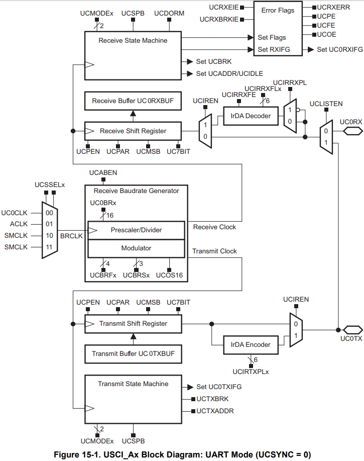
BCSCTL1 = CALBC1_1MHZ;
DCOCTL = CALDCO_1MHZ;
UCA0CTL1 |= UCSSEL_2; // SMCLK
UCA0BR0 = 8; // 1MHz 115200
UCA0BR1 = 0; // 1MHz 115200
UCA0MCTL = UCBRS2 + UCBRS0; // Modulation UCBRSx = 5
UCA0CTL1 &= ~UCSWRST; // **Initialize USCI state machine**
IE2 |= UCA0RXIE; // Enable USCI_A0 RX interrupt
However, I wanted to use a faster clock speed up to 16MHz.
I have the MSP-EXP430G2 and I use CCS 8 on Windows 10. The 32kHz crystal is soldered on my launchpad.
These are my questions;
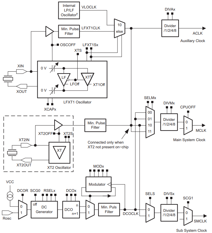
1. According to the baud rate formula, if I choose ACLK,
UCA0CTL1 |= UCSSEL_1; // ACLK
UCA0BR0 = 0; // N = 32768 / 115200 = 0.28444, INT(N) = 0
UCA0BR1 = 2; // round( ( N – INT(N) ) × 8 )
this is my result.
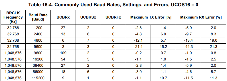
However, can I use that? I think this won't work since UCA0BR0 is equal to zero and I cannot find that combination on this table.
So, if I choose ACLK for the baud rate generator, I cannot create a 115200 baud rate?
2. If I choose DCO as 16MHz and SMCLK for the baud rate generator,
BCSCTL1 = CALBC1_16MHZ;
DCOCTL = CALDCO_16MHZ;
BCSCTL2 = DIVS_0; // SMCLK Divider 1

UCA0CTL1 |= UCSSEL_2; // SMCLK
UCA0BR0 = 138; // N = 16MHz / 115200 = 138.8888...
UCA0BR1 = 7; // round(7.111)
UCA0MCTL = UCBRS2 + UCBRS0;               // Modulation UCBRSx = 5
UCA0CTL1 &= ~UCSWRST; // **Initialize USCI state machine**
IE2 |= UCA0RXIE; // Enable USCI_A0 RX interrupt
Are these the correct values for both UCA0BR0 and UCA0BR1?
3. Suppose the above values were correct.
BCSCTL1 = CALBC1_16MHZ;
DCOCTL = CALDCO_16MHZ;
BCSCTL2 = DIVS_3; // SMCLK Divider 8, SMCLK = 2MHz

UCA0CTL1 |= UCSSEL_2; // SMCLK
UCA0BR0 = 17; // N = 2MHz / 115200 = 17.361111...
UCA0BR1 = 3; // round(2.888)
UCA0MCTL = UCBRS2 + UCBRS0;               // Modulation UCBRSx = 5
UCA0CTL1 &= ~UCSWRST; // **Initialize USCI state machine**
IE2 |= UCA0RXIE; // Enable USCI_A0 RX interrupt
This will also generate a 115200 baud rate. I'm curious whether CASE 2 (SMCLK = DCO) is better,
for power consumption / clock error / etc,
or CASE 3 (SMCLK = DCO / 8) is better. Or are there any difference?

