


Hi! I'm coming back to this issue with new updates.
I have reviewed the schematics and create a new PCB, I will attach the schematics here.
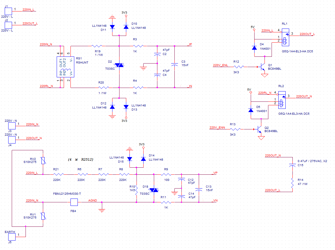
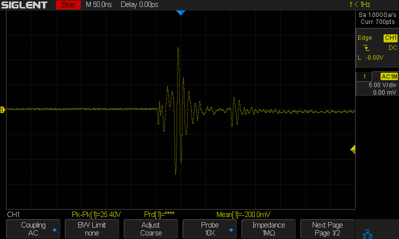
The problem remains the same, it seems that the clamping diodes are worsen the situation, the voltage spikes have higher values when the diodes are present.
(VP - VN) SIGNAL
I will try to place some Zener diodes, but I guess they will not be fast enough to catch the spike.
It seems that the problem have no resolution, at least not in this configuration. The size of PCB is 75mmx50mm and I think moving the relays way apart from the actual PCB will reduce also de voltage spikes influence.
