This thread has been locked.

If you have a related question, please click the "Ask a related question" button in the top right corner. The newly created question will be automatically linked to this question.

MSP430FR2633: Unable to get proper value at Start and End points of slider.

Part Number: MSP430FR2633

Hello,

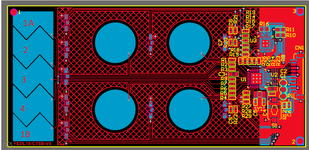
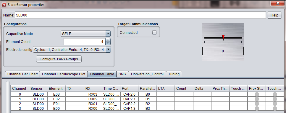
             I have a designed a pcb which consist of 1 slider with CAP I/O as defined below. In capativate design center I have assigned the CAP I/O's as shown below in the picture. The problem here is unable to get proper values at the start and end points. ie the slider shows approximate 700 to 800 value at both the ends and at one end (ie start of slno 5 (Element 0))  the slider shows approximate 25 to 30 value. Resolution is 1000. and rest parameters are default values. 

Tool versions 

CCS v8.2.0.00007

captivate design center v1.6

PCB Assignments
Slno. Elements CAP I/O
1 0 CAP 1.3
2 1 CAP 2.2
3 2 CAP 2.1
4 3 CAP 2.0
5 0

CAP 1.3

In Design center 

B.R

Gourav

  • Hello,

    Is it mandatory to use these below CAP I/O's for slider???

    SL.No. Elements CAP I/O's
    1 0 0.2
    2 1 1.2
    3 2 2.2
    4 3 3.2
    5 0 0.2

    B.R

    Gourav

  • Hi Gourav,

    No, it is not mandatory to use the CAP I/O you have listed. You can manually assign your elements to any of the CAP I/Os.

    Could you provide the layout and schematic of your slider design?

    Thanks,

    Mitch

  • Hi Mitch,

                     Here is the Schematic and PCB layout one addition is that the elements have silk screen on them.

    B.R

    Gourav

  • Hi Gourav,

    Thank you for providing that information. I have a couple more questions for you.

    I renamed the elements in your design for easier reference in my questions (1A, 2, 3, 4, 1B):

    1. Can you tell me what value you get when you touch each element individually? For example, when you place your finger on element 1A, what value between 0 - 1000 do you see? I am trying to visually understand what you mean by: "ie the slider shows approximate 700 to 800 value at both the ends and at one end (ie start of slno 5 (Element 0))  the slider shows approximate 25 to 30 value." Can you clarify this a bit more?

    2. What are the dimensions of the slider? 

    If your finger can fit inside element 1A or 1B without touching another adjacent element, the algorithm may not know which end of the slider you are on. It looks like you have incorporated a good amount of digitization between the elements, but I'd like to double check your dimensions.

    Thanks,

    Mitch

  • Hi Mitch.

                           Below table describes the variation of the slider values. The Dimension  of slider is 12 mm X 38.628 mm. Is there any thing to do with silkscreen on the slider??. Below is the picture of the PCB .

    Approximate position of finger on slider Slider Values 
    End of 1A 747-720
    Near 1A 720-600
    Between 1A and 2 680-570
    Near 2 570-510
    Between 2 and 3 480-410
    Near 3 300-280
    Between 3 and 4 270-15
    Near 4 920-990
    Between 4 and 1B 820-920
    Near 1B 755-800
    End of 1B 750-755

    B.R.

    Gourav

  • Hi Mitch,
    I had previously designed PCB with same dimensions of the slider and with 4 buttons, the CAP I/O'S were same as used in the capacitive developement board BSWP. The slider had worked well ie:-i got the proper values as 0 at 1A and 1000 at 1B. The only change with this PCB is the CAP I/O's which I have mentioned in above conversation.

    B.R.
    Gourav
  • Hello Gourav,

    Thanks for providing all the detail information.
    So you designed the same slider with the same layout previously with the only difference is the CAP I/O assignment and that slider has no issues right?

    Do you mind share with us your code? If you do not feel comfortable to share the whole project I just need to see the CAPT_UserConfig.c and CAPT_UserConfig.h file under your CAPT_UserConfig folder. Based on your CapTIvate Design Center configuration I do not see anything issue but I just want to see the code to make sure the elements are being assigned correctly.

    Thanks,
    Yiding
  • Hi Yiding,

                      Yes I had no issues with the slider in previous version of PCB. Below are the CAPT_UserConfig.c and CAPT_UserConfig.h files for the current version of pcb with slider issues.

    B.R.

    Gourav

    3660.CAPT_UserConfig.c
    /* --COPYRIGHT--,BSD
     * Copyright (c) 2017, Texas Instruments Incorporated
     * All rights reserved.
     *
     * Redistribution and use in source and binary forms, with or without
     * modification, are permitted provided that the following conditions
     * are met:
     *
     * *  Redistributions of source code must retain the above copyright
     *    notice, this list of conditions and the following disclaimer.
     *
     * *  Redistributions in binary form must reproduce the above copyright
     *    notice, this list of conditions and the following disclaimer in the
     *    documentation and/or other materials provided with the distribution.
     *
     * *  Neither the name of Texas Instruments Incorporated nor the names of
     *    its contributors may be used to endorse or promote products derived
     *    from this software without specific prior written permission.
     *
     * THIS SOFTWARE IS PROVIDED BY THE COPYRIGHT HOLDERS AND CONTRIBUTORS "AS IS"
     * AND ANY EXPRESS OR IMPLIED WARRANTIES, INCLUDING, BUT NOT LIMITED TO,
     * THE IMPLIED WARRANTIES OF MERCHANTABILITY AND FITNESS FOR A PARTICULAR
     * PURPOSE ARE DISCLAIMED. IN NO EVENT SHALL THE COPYRIGHT OWNER OR
     * CONTRIBUTORS BE LIABLE FOR ANY DIRECT, INDIRECT, INCIDENTAL, SPECIAL,
     * EXEMPLARY, OR CONSEQUENTIAL DAMAGES (INCLUDING, BUT NOT LIMITED TO,
     * PROCUREMENT OF SUBSTITUTE GOODS OR SERVICES; LOSS OF USE, DATA, OR PROFITS;
     * OR BUSINESS INTERRUPTION) HOWEVER CAUSED AND ON ANY THEORY OF LIABILITY,
     * WHETHER IN CONTRACT, STRICT LIABILITY, OR TORT (INCLUDING NEGLIGENCE OR
     * OTHERWISE) ARISING IN ANY WAY OUT OF THE USE OF THIS SOFTWARE,
     * EVEN IF ADVISED OF THE POSSIBILITY OF SUCH DAMAGE.
     * --/COPYRIGHT--*/
    
    
    // Generated by Captivate Design Center v1_60_00_00 on Mon Dec 24 11:51:02 IST 2018
    
    
    //*****************************************************************************
    // CAPT_UserConfig.c
    //
    // \version 1.60.00.03
    // Released on November 22, 2017
    //
    //*****************************************************************************
    
    //*****************************************************************************
    //
    // NOTE: This is an automatically generated source code file!  The Captivate
    // Design Center generates the User Configuration file automatically based
    // upon the sensor layout that was created.
    //
    // Changes to this file will be OVERWRITTEN if a you select
    // "Update Existing Project" under "Generate Source Code" in the Design Center.
    //
    // To avoid interference with the code generation process, keep ALL application
    // code external to this file.
    //
    //*****************************************************************************
    
    #include "CAPT_UserConfig.h"
    
    //*****************************************************************************
    //
    //! Captivate Element Definitions
    //! All elements in this application are defined below.
    //! Each element has 3 components:
    //!  1) a raw count array (One index per freq. scanned) (uint16_t)
    //!  2) a tuning array (One index per freq. scanned) (tCaptivateElementTuning)
    //!  3) a element structure (tElement)
    //
    //*****************************************************************************
    // Sensor: SLD00, Element: E03
    uint16_t SLD00_E03_RawCnts[CAPT_SELF_FREQ_CNT];
    tCaptivateElementTuning SLD00_E03_Tuning[CAPT_SELF_FREQ_CNT];
    tElement SLD00_E03 =
    {
        .ui8RxPin = 0,
        .ui8RxBlock = 2,
        .ui8TouchThreshold = 10,
        .pRawCount = SLD00_E03_RawCnts,
        .pTuning = SLD00_E03_Tuning,
    };
    
    // Sensor: SLD00, Element: E02
    uint16_t SLD00_E02_RawCnts[CAPT_SELF_FREQ_CNT];
    tCaptivateElementTuning SLD00_E02_Tuning[CAPT_SELF_FREQ_CNT];
    tElement SLD00_E02 =
    {
        .ui8RxPin = 1,
        .ui8RxBlock = 2,
        .ui8TouchThreshold = 10,
        .pRawCount = SLD00_E02_RawCnts,
        .pTuning = SLD00_E02_Tuning,
    };
    
    // Sensor: SLD00, Element: E01
    uint16_t SLD00_E01_RawCnts[CAPT_SELF_FREQ_CNT];
    tCaptivateElementTuning SLD00_E01_Tuning[CAPT_SELF_FREQ_CNT];
    tElement SLD00_E01 =
    {
        .ui8RxPin = 2,
        .ui8RxBlock = 2,
        .ui8TouchThreshold = 10,
        .pRawCount = SLD00_E01_RawCnts,
        .pTuning = SLD00_E01_Tuning,
    };
    
    // Sensor: SLD00, Element: E00
    uint16_t SLD00_E00_RawCnts[CAPT_SELF_FREQ_CNT];
    tCaptivateElementTuning SLD00_E00_Tuning[CAPT_SELF_FREQ_CNT];
    tElement SLD00_E00 =
    {
        .ui8RxPin = 3,
        .ui8RxBlock = 1,
        .ui8TouchThreshold = 10,
        .pRawCount = SLD00_E00_RawCnts,
        .pTuning = SLD00_E00_Tuning,
    };
    
    
    //*****************************************************************************
    //
    //! Captivate Time Cycle Definitions
    //! All time cycles in this application are defined below.  Time cycles are
    //! groups of elements that are measured together in parallel in one time slot.
    //! Each cycle has 2 components:
    //!  1) an element pointer array to the member elements (tElement*)
    //!  2) a cycle structure (tCycle)
    //
    //*****************************************************************************
    // Time Cycle: SLD00_C00
    tElement* SLD00_C00_Elements[1] =
    {
        &SLD00_E03,
    };
    tCycle SLD00_C00 =
    {
        .ui8NrOfElements = 1,
        .pElements = SLD00_C00_Elements,
    };
    
    // Time Cycle: SLD00_C01
    tElement* SLD00_C01_Elements[1] =
    {
        &SLD00_E02,
    };
    tCycle SLD00_C01 =
    {
        .ui8NrOfElements = 1,
        .pElements = SLD00_C01_Elements,
    };
    
    // Time Cycle: SLD00_C02
    tElement* SLD00_C02_Elements[1] =
    {
        &SLD00_E01,
    };
    tCycle SLD00_C02 =
    {
        .ui8NrOfElements = 1,
        .pElements = SLD00_C02_Elements,
    };
    
    // Time Cycle: SLD00_C03
    tElement* SLD00_C03_Elements[1] =
    {
        &SLD00_E00,
    };
    tCycle SLD00_C03 =
    {
        .ui8NrOfElements = 1,
        .pElements = SLD00_C03_Elements,
    };
    
    
    //*****************************************************************************
    //
    //! Captivate Sensor Definitions
    //! All sensors in this application are defined below.  Sensors are
    //! groups of time cycles that utilize raw measurement data to create an
    //! abstract sensor type, such as a button, slider, wheel, or prox sensor.
    //! Each sensor has 3 components:
    //!  1) a cycle pointer array to the member time cycles (tCycle*)
    //!  2) a sensor-specific parameter structure (tGenericSensorParams)
    //!  3) a sensor structure (tSensor)
    //
    //*****************************************************************************
    //Sensor: SLD00
    const tCycle* SLD00_Cycles[4] =
    {
        &SLD00_C00,
        &SLD00_C01,
        &SLD00_C02,
        &SLD00_C03,
    };
    
    tSliderSensorParams SLD00_Params =
    {
        .ui8TotalElements = 4,
        .ui16Resolution = 1000,
        .SliderBeta = 100,
        .SliderLower = 0,//50,//0,
        .SliderUpper = 999,//960,//845,
        .SliderAlgorithm = eVectors,
        .SliderFilterEnable = true,
    };
    
    tSensor SLD00 =
    {
        // Basic Properties
        .TypeOfSensor = eSlider,
        .SensingMethod = eSelf,
        .DirectionOfInterest = eDOIDown,
        .pvCallback = NULL,
        .ui8NrOfCycles = 4,
        .pCycle = SLD00_Cycles,
        .pSensorParams = (tGenericSensorParams*)&SLD00_Params,
        // Conversion Control Parameters
        .ui16ConversionCount = 500,
        .ui16ConversionGain = 100,
        .ui8FreqDiv = 2,
        .ui8ChargeLength = 0,
        .ui8TransferLength = 0,
        .bModEnable = false,
        .ui8BiasControl = 3,
        .bCsDischarge = true,
        .bLpmControl = false,
        .ui8InputSyncControl = 0,
        .bTimerSyncControl = false,
        .bIdleState = true,
        // Tuning  Parameters
        .ui16ProxThreshold = 10,
        .ui16NegativeTouchThreshold = 30,
        .ui16ErrorThreshold = 8191,
        .ui16TimeoutThreshold = 65535,
        .ProxDbThreshold.DbIn = 1,
        .ProxDbThreshold.DbOut = 0,
        .TouchDbThreshold.DbIn = 1,
        .TouchDbThreshold.DbOut = 0,
        .bCountFilterEnable = false,
        .ui8CntBeta = 1,
        .bSensorHalt = false,
        .bPTSensorHalt = true,
        .bPTElementHalt = true,
        .ui8LTABeta = 7,
        .bReCalibrateEnable = true,
    };
    
    
    #if (CAPT_CONDUCTED_NOISE_IMMUNITY_ENABLE==true)
    //*****************************************************************************
    //
    //! \var g_EMCConfig
    //! This structure stores the EMC configuration for this application.
    //
    //*****************************************************************************
    const tEMCConfig g_EMCConfig =
    {
    	// Conversion Style
    	.selfModeConversionStyle = eMultiFrequency,
    	.projModeConversionStyle = eMultiFrequencyWithOutlierRemoval,
    	
    	// Oversampling Style
    	.selfModeOversamplingStyle = eNoOversampling,
    	.projModeOversamplingStyle = eNoOversampling,
    	
    	// Jitter Filter Enable
    	.bJitterFilterEnable = true,
    	
    	// Noise Thresholds and Calibration Noise Limits
    	.ui8NoiseThreshold = 20,
    	.ui16CalibrationNoiseLimit = 10,
    	.ui8CalibrationTestSampleSize = 8,
    		
    	// Dynamic Threshold Adjustment Parameters
    	.bEnableDynamicThresholdAdjustment = true,
    	.ui8MaxRelThreshAdj = 76,
    	.ui8NoiseLevelFilterEntryThresh = 40,
    	.ui8NoiseLevelFilterExitThresh = 0,
    	.ui8NoiseLevelFilterDown = 6,
    	.ui8NoiseLevelFilterUp = 1,
    	.coeffA = _IQ31(0.0065),
    	.coeffB = _IQ31(0.050)
    };
    #endif
    
    //*****************************************************************************
    //
    //! \var g_pCaptivateSensorArray
    //! This array allows for indexed access to any
    //! sensor in the configuration.
    //
    //*****************************************************************************
    tSensor* g_pCaptivateSensorArray[CAPT_SENSOR_COUNT] =
    {
        &SLD00,
    };
    
    
    //*****************************************************************************
    //
    //! \var g_uiApp
    //! This structure stores the global settings for this application.
    //
    //*****************************************************************************
    tCaptivateApplication g_uiApp =
    {
        .state = eUIActive,
    	.pSensorList = &g_pCaptivateSensorArray[0],
        .ui8NrOfSensors = CAPT_SENSOR_COUNT,
        .ui8AppLPM = LPM3_bits,
        .bElementDataTxEnable = true,
        .bSensorDataTxEnable = true,
        .ui16ActiveModeScanPeriod = 33,
        .ui16WakeOnProxModeScanPeriod = 100,
        .ui16InactivityTimeout = 32,
        .ui8WakeupInterval = 5,
    };
    

    CAPT_UserConfig.h

  • Hello yiding ,
    Is there anything to do parallel group and "controller USE MODE" in capacitive design centre??
    B.R.
    Gourav
  • Hello Gourav,

     Sorry for the late reply due to the holiday.

    I checked your code with your layout but still did not see anything that could cause your issue.The only way for me to reproduce what you seen with the slider position issue is that if the slider elements are in wrong order but I checked your code the slider elements are in the right order.

    Let’s say if I have a slider with 4 electrodes (RX0, RX1, RX2, RX3) arranged like this:

    My elements order should be RX0 = E0, RX1=E1, RX2=E2, RX3=E3 or RX0 = E3, RX1=E0, RX2=E1, RX3=E2. If the electrodes are in wrong order, you will see the wrong slider position like what you are seeing with 900 near RX3. But I see you have the correct elements configuration in CapTIvate Design Center and also in your code.

    I will work with the team to see if there is anything else that can cause your issue.

    Ideally we recommend user to design the slider with 1 pin from each block so you can parallel scan all 4 slider elements at the same time which could reduce the parasitic capacitance because all elements are always scanning at the same time instead of connecting to GND when others are scanning, this could help with the slider linearity. Even though we recommend this but if you do not have all elements scanning in parallel it should not cause the issue you are seeing. Again, I will work with the team once they back from holiday tomorrow to see what else could cause your issue. And can you check see if there is anything else changed on the PCB comparing to the version that worked for you before?

    Thanks for your patience and cooperation. 

    Yiding

  • Hi Yiding,

                    I have rechecked the layout and compared with prior versions there is no change except the capios. The slider position issue is been resolved. the solution is assigning the parallel group to respective element. like this

    B0=RX00=E0,

    B1=RX01=E1

    B2=RX02=E2

    B3=RX03=E3

    Does this configuration cause any issues in the future??.

    I would also like to know more about "Parallel Group" and "Controller USE MODE" in Capacitive Design Center.

    Is there a way to use multi-function CAPI/O pins as GPIO with buttons and slider included??

    B.R.

    Gourav

  • Hello Gourav,

    I am glad that was able to solve your issue and it should not cause any issues in the future.

    For "Parallel Group", CapTIvate™ devices with more than one sensing block can measure one input from each block in parallel. For example, the MSP430FR2633 implements four sensing blocks, each with four CapTIvate™ I/O pins. This allows up to 4 inputs to be measured at the same time in a single measurement cycle. Measuring the inputs in parallel reduces both the measurement time and power consumption. Selecting a cell in the parallel group column will bring up a pull-down menu that allows This column allows the user to modify which pins are assigned to each parallel sense group.

    The default is: 

    CAP0.0 = B0, CAP0.1 = B1, CAP0.2 = B2, CAP0.3 = B3

    CAP1.0 = B0, CAP1.1 = B1, CAP1.2 = B2, CAP1.3 = B3

    CAP2.0 = B0, CAP2.1 = B1, CAP2.2 = B2, CAP2.3 = B3

    CAP3.0 = B0, CAP3.1 = B1, CAP3.2 = B2, CAP3.3 = B3

    4 pins in the same scan group will be scanned in parallel. For example, CAP0.0, CAP1.0, CAP2.0 and CAP3.0 in group B0 will be scanned in parallel. 

    You can assign the CAP IOs to different scan group to have different combinations of CAP IOs scan in parallel. So if I change CAP0.0 = B3, and CAP0.3 = B0 then CAP0.0, CAP1.3, CAP2.3, and CAP3.3 will be scanned in parallel. You can also refer to the "Time Cycles" on the right side to see which CAP IOs are in the same time cycle which means they will be scanned in parallel. 

    For "Controller USE MODE", Selecting a cell in the controller use mode column will bring up a pull-down menu that allows the user to control the usage mode of the port. The “Use Mode” column will be updated to display any restrictions made a controller pin.

    • Unrestricted: No restriction applied to this pin.
    • Reserved: No sensor port may be assigned to this pin
    • RX only: Only sensor RX ports may be assigned to this pin
    • TX only: Only sensor TX ports may be assigned to this pin
    • SELF only: Only self capacitance sensor ports may be assigned to this pin
    • MUTUAL only: Only mutual capacitance sensor ports may be assigned to this pin

    Please let me know if you have any questions.

    Thanks,

    Yiding

  • Hi Yiding,


    Yiding Luo said:
    Measuring the inputs in parallel reduces both the measurement time and power consumption.
     

    Is this same for buttons, proximity sensors and wheel?? lets say that we have 10 buttons, so the assignment would be like this,

    4 buttons =B0 parallel Group,

    4 buttons =B1 parallel Group,

    2 buttons =B2 parallel Group,

    Is there an option to implement multi touch for buttons, slider,wheel??

  • Hi Gourav,

    Yiding is away on vacation. He will respond when he returns. Sorry for the delay.

    Thanks,

    Mitch
  • Hello Gourav,

    Yes, you are correct about the parallel scanning for the 10 buttons.

    Multi-touch for buttons is implemented by default, meaning if one or all buttons are pressed simultaneously, all touches are reported (as can be seen in the CapTIvate design center when you are "tuning" the sensors). It's up to the application software, the code you add to a callback function, that determines if you want to see only one (a.k.a dominant button) or see all the buttons touched.

    Sliders and wheels, however, don't work that way. Based on the finger touching the slider or wheel, the algorithm attempts to determine it's position. If you have more than one finger, the algorithm will think the position is somewhere between the two finger points of contact.

**Attention** This is a public forum