This thread has been locked.

If you have a related question, please click the "Ask a related question" button in the top right corner. The newly created question will be automatically linked to this question.

Implementation of a Three-Phase Electronic Watt-Hour Meter Using the MSP430F677x(A)

Hi,

This is with reference to application note: Implementation of a Three-Phase Electronic Watt-Hour Meter Using the MSP430F677x(A) from TI.

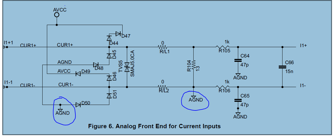
In above document in section 3.2.2 :  Hardware implementation :Current Inputs:

I want to ask why there is ground interface at negative terminal of current sensing.

This is because ,as any ways current has to be returned to its return path, and also we are interfacing differential signal -double ended signal to controller then why there is ground interface is there.

.

Please find attached image for reference.

Please explain

Regards

Girish Brahme

  • Grish,
    In a 3-phase application for current sensing, we cannot use shunt resistors unless there is a electrical isolation between each phase. Hence the way to go forward is to use current transformers or Rogowski coils as current sensors. Once one of these sensors are used, it is important the one of the terminals on the secondary side must be referenced to a known voltage and cannot remain floating. Hence the negative terminal has been connected to AGND. Once this is done, the differential output on the secondary of current transformer is correctly measured for any changes of primary currents for each phases. Also, on the voltage side, the voltage divider is connected between each Line voltage and Neutral. The same applies and we cannot have the output of the voltage divider floating. Hence the negative pin is also connected to the same GND (AGND).

    Additionally, if you are doing a single-phase design and using a shunt-resistor, the need for connected one of the terminals to GND is not required.
    Let me know if you need further clarification on this topic.

    Thanks
    Kripa
  • Hi,

    Thanks for your information.

    Regards

    Girish Brahme

  • Dear sir,

    Thanks for your feedback.

    According to your comment AGND is used as reference it to known voltage so that it would not remain floating.

    But I have one doubt: As you are connecting that terminal to ground, then potential at negative terminal would be always zero.

    So how it could measure differential sensing ? as one end will be always connected ground.

    Negative part of signal would be always at ground zero potential.

    Please explain.

    Thanks,

    Girish Brahme

  • Girish,
    Yes, this could be confusing, but essentially connecting to AGND is purely to tie it to a known voltage, not necessarily zero potential. For test purposes, typically, AGND is zero, but it is not absolutely true all the time. Also, irrespective of the actual voltage of AGND, the sigma-delta is still doing a differential conversion. As an example, you can actually connect the -ve terminal to any known voltage on the board, and the converter will do the differential conversion based on that connection. Thanks

    Kripa

**Attention** This is a public forum