This thread has been locked.

If you have a related question, please click the "Ask a related question" button in the top right corner. The newly created question will be automatically linked to this question.

MSP432P401V: fatsdraw project sd card driver

Part Number: MSP432P401V

Dear all,

I saw the fatsdraw project config the MCLK and SMCLK at 10M HZ, SPI is using SMCLK as peripheral clock.

when I change the SMCLK to 9M and 11M or other frequency, the project can't find the external SD card, only SPI CLK is 10M hz , the code can find the external sd card.

Why? 

  • Hello Michael,

    From the TRM, the DIVS bits should be adjusted to get the desired Clock rate for SMCLK. Look at the image below:

    From the Board file MSP_EXP432P401R.c, looks like the myPerfLevels is being used by the application to select clocks. I have included that section of code below. From this code .DIVS is set to divide by 1. Can you confirm that bit field DIVS value (in the CSCTL1) bit is set according to what the expected SMCLK rate is?

    PowerMSP432_PerfLevel myPerfLevels[] = {{
          .activeState = PCM_AM_DCDC_VCORE0,
          .VCORE = 0,
          .clockSource = CS_DCOCLK_SELECT,
          .DCORESEL = CS_DCO_TUNE_FREQ,
          .tuneFreqDCO = 10000000,
          .SELM = CS_DCOCLK_SELECT,
          .DIVM = CS_CLOCK_DIVIDER_1,
          .SELS = CS_DCOCLK_SELECT,
          .DIVHS = CS_CLOCK_DIVIDER_1,
          .DIVS = CS_CLOCK_DIVIDER_1,
          .SELB = CS_REFOCLK_SELECT,
          .SELA = CS_REFOCLK_SELECT,
          .DIVA = CS_CLOCK_DIVIDER_1,
          .flashWaitStates = 0,
          .enableFlashBuffer = true,
          .MCLK = 10000000,
          .HSMCLK = 10000000,
          .SMCLK = 10000000,
          .BCLK = 32768,
          .ACLK = 32768,
    
    }};

    Thanks,

    Sai

    Edit:

    The above mentioned myPerfLevels in the MSP_EXP432P401R.c file is not used by the fatsdraw. This is because of the element .initialPerfLevel being set performance level of 2 in the MSP_EXP432P401R.c file.

    const PowerMSP432_ConfigV1 PowerMSP432_config = {
        .policyInitFxn = &PowerMSP432_initPolicy,
        .policyFxn = &PowerMSP432_sleepPolicy,
        .initialPerfLevel = 2,
        .enablePolicy = true,
        .enablePerf = true,
        .enableParking = true,
        .customPerfLevels = myPerfLevels,
        .numCustom = sizeof(myPerfLevels) / sizeof(PowerMSP432_PerfLevel)
    };

    To use myPerfLevels the performance level should be set to 4. The following API can be used:

        Power_releaseConstraint(PowerMSP432_DISALLOW_PERFLEVEL_4);
        Power_setPerformanceLevel(4);

  • Sai,

    Thanks for your follow up, but I don't think you get my point.

    I know the setting how to config the Clock, my question is when I changed the DCO frequency, the MCLK, SMCLK, HSMCLK also should changed, but why SMCLK changed to other frequency(not 10M hz), the sd card can't be find anymore? 


  • Sai,

    You misunderstand my question, I don't ask the clock configuration in the thread.

    I am asking why MCLK and SMCLK changed, SDcard can't be found any more?

    I know that there should be a 10ms polling card operation for SD card, but not found the related code in the example and don't sure if this is why I changed the MCLK and the timer chaned, so can't found the SD card.

    There is another thread ask for clock configuration, 

    https://e2e.ti.com/support/microcontrollers/msp430/f/166/p/805205/2980955#2980955

    Many thanks!

  • Hello Michael,

    It is not clear to me what you have changed, what you are expecting and what is actually occurring. Can you please provide these details?

    • Which clock settings are you changing from the default example?
    • What is your expectation with this change?
    • What is actually occurring?

    Thanks,

    Sai

  • Sai,

    Below configuation. 

    /* Custom performance level for SPI Master Example */
    PowerMSP432_PerfLevel myPerfLevels[] = {{
    .activeState = PCM_AM_DCDC_VCORE0,
    .VCORE = 0,
    .clockSource = CS_DCOCLK_SELECT,
    .DCORESEL = CS_DCO_TUNE_FREQ,
    .tuneFreqDCO = 11000000,
    .SELM = CS_DCOCLK_SELECT,
    .DIVM = CS_CLOCK_DIVIDER_1,
    .SELS = CS_DCOCLK_SELECT,
    .DIVHS = CS_CLOCK_DIVIDER_1,
    .DIVS = CS_CLOCK_DIVIDER_1,
    .SELB = CS_REFOCLK_SELECT,
    .SELA = CS_REFOCLK_SELECT,
    .DIVA = CS_CLOCK_DIVIDER_1,
    .flashWaitStates = 0,
    .enableFlashBuffer = true,
    .MCLK = 11000000,
    .HSMCLK = 11000000,
    .SMCLK = 11000000,
    .BCLK = 32768,
    .ACLK = 32768,

    }};

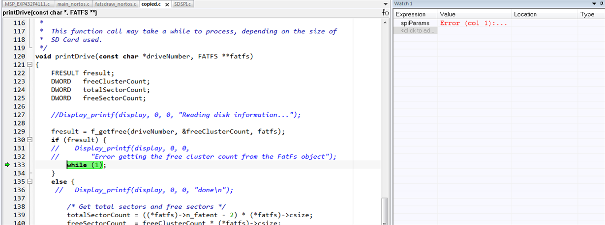
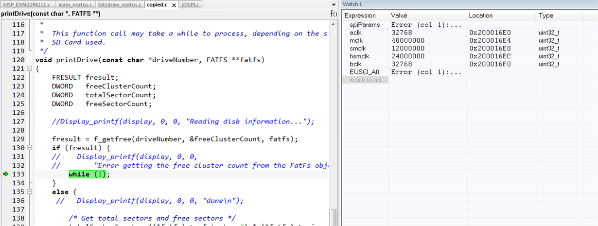
    the code get into while() show as below and can't work any more.

    fresult = f_getfree(driveNumber, &freeClusterCount, fatfs);
    if (fresult) {
    Display_printf(display, 0, 0,
    "Error getting the free cluster count from the FatFs object");
    while (1);
    }

    My Clock system expecting is show in another thread. https://e2e.ti.com/support/microcontrollers/msp430/f/166/p/805205/2980955#2980955, and can read the external sd card.

  • Hello Michael,

    I think I understand the issue now. I will have to try this out. I will get back on Tuesday (6/11) on this issue. Hope the timing works!

    There is a SimpleLink Academy lab on custom power performance: http://dev.ti.com/tirex/explore/node?node=ABmGjWlxaYzbSGJJM6AZqA__z-lQYNj__LATEST

    Please refer to it in the mean time to see if addresses your issue.

    Regards,

    Sai

  • Hello Michael,

    I have the following feedback after reviewing this post with my colleague.

    • Using Custom performance level: By default the custom performance level myPerfLevels in the MSP_EXP432P401R.c file is not used. I have update the my first response to this thread to show how the custom performance level can be used.
    • MCLK cannot be set to more than 10MHz with VCORE set to 0. See the relevant section from Datasheet below:
    • Also note that the SD SPI driver sets the clock to 2.5MHz. The SMCLK has to be a multiple of this (2.5Mhz) frequency for the SPI to operate at 2.5MHz. If not the desired SPI frequency will not be set.

    Thanks,

    Sai

  • Sai,

    Thanks for you reply, well noted but one more addition question

    1. why SD SPI driver need to sets the clock to 2.5MHz, or I can redefine ?

    2. Where I can find the SD SPI clock define?

    I only find that SPI clock came from  

    /*
    * =============================== SPI ===============================
    */
    #include <ti/drivers/SPI.h>
    #include <ti/drivers/spi/SPIMSP432DMA.h>

    SPIMSP432DMA_Object spiMSP432DMAObjects[MSP_EXP432P4111_SPICOUNT];

    /*
    * NOTE: The SPI instances below can be used by the SD driver to communicate
    * with a SD card via SPI. The 'defaultTxBufValue' fields below are set to 0xFF
    * to satisfy the SDSPI driver requirement.
    */
    const SPIMSP432DMA_HWAttrsV1 spiMSP432DMAHWAttrs[MSP_EXP432P4111_SPICOUNT] = {
    { //sd card operation
    .baseAddr = EUSCI_A2_BASE,
    .bitOrder = EUSCI_A_SPI_MSB_FIRST,
    .clockSource = EUSCI_A_SPI_CLOCKSOURCE_SMCLK,

    in the project,  SMCLK = 10M hz.

  • Sai,

    I found the define in sdspi.c

    /* Check to see if a card type was determined */
    if (cardType == SD_NOCARD) {
    status = SD_STATUS_ERROR;
    }
    else {
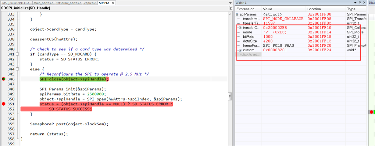
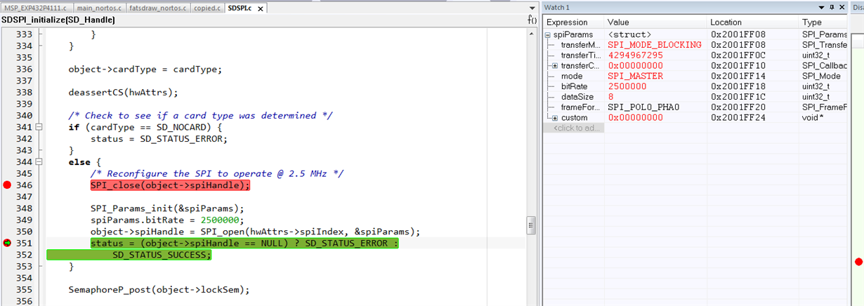
    /* Reconfigure the SPI to operate @ 2.5 MHz */
    SPI_close(object->spiHandle);

    SPI_Params_init(&spiParams);
    spiParams.bitRate = 2500000;
    object->spiHandle = SPI_open(hwAttrs->spiIndex, &spiParams);
    status = (object->spiHandle == NULL) ? SD_STATUS_ERROR :
    SD_STATUS_SUCCESS;
    }

    As the SMCLK is 12M hz, I set the spi at 2M hz

    spiParams.bitRate = 2000000;

    Still can't pulling the sd card. Could you help to point out the problem.

    --------------------------------------------------------------------------------------------------------------------------

    After I set the MCLK and SMCLK, I use below code to check the CLK, SMCLK is 12M hz.

    static volatile uint32_t aclk, mclk, smclk, hsmclk, bclk;
    aclk = MAP_CS_getACLK();
    mclk = MAP_CS_getMCLK();
    smclk = MAP_CS_getSMCLK();
    hsmclk = MAP_CS_getHSMCLK();
    bclk = MAP_CS_getBCLK();

    Before reconfig the SD SPI clock to 2.5M HZ, SDSPI_initalize( ) function can found the sd card,

    SD_CardType = SD_SDHC;

    )

  • Sai,

    Please help to see my future testing

  • Sai.

    Another testing for your information.

    Make the MCLK = 40M HZ

    SMCLK = 10M HZ

    the code still goes into Error getting the free cluster count from the FatFs object

    void printDrive(const char *driveNumber, FATFS **fatfs)

    {

        FRESULT fresult;

        DWORD   freeClusterCount;

        DWORD   totalSectorCount;

        DWORD   freeSectorCount;


        //Display_printf(display, 0, 0, "Reading disk information...");


        fresult = f_getfree(driveNumber, &freeClusterCount, fatfs);

        if (fresult) {

        //    Display_printf(display, 0, 0,

        //        "Error getting the free cluster count from the FatFs object");

            while (1);

    }

  • Michael,

        For the MSP432P401V, an MCLK of 40Mhz requires that the device use Vcore1 and that the flash wait-states be set to at least 2.  If the SMCLK is set to 10Mhz then this would result in a SPI BR scale of 25.  Can you look at the registers in the CCS and verify that these are the states of the device?

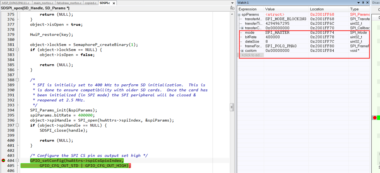
        /*
         * SPI is initially set to 400 kHz to perform SD initialization.  This is
         * is done to ensure compatibility with older SD cards.  Once the card has
         * been initialized (in SPI mode) the SPI peripheral will be closed &
         * reopened at 2.5 MHz.
         */
        SPI_Params_init(&spiParams);
        spiParams.bitRate = 400000;
        object->spiHandle = SPI_open(hwAttrs->spiIndex, &spiParams);
        if (object->spiHandle == NULL) {
            SDSPI_close(handle);
    
            return (NULL);
        }

    Regards,

    Chris

  • Chris,

    1. Well noted about  use Vcore1 and that the flash wait-states be set to at least 2 when I want to use 40M HZ MCLK and 10M HZ SMCLK, many thanks !

    2. I don't t understand you words, SMCLK is set to 10Mhz then this would result in a SPI BR scale of 25.

       10M HZ SMCLK is the fatsdraw project define, 2.5M hz SPI is also the project define.

       MCLk = 10M HZ, SMCLK = 10M HZ, the project can polling the sd card success,

       MCLk = 40M HZ, SMCLK = 10M HZ, the project can polling the sd card success,

       i don't know why.

      Customer need high MCLK frequency.

    3.Register  information as you wish.

  • Chris,

    One mistake 

    MCLk = 10M HZ, SMCLK = 10M HZ, the project can polling the sd card success,

     MCLk = 40M HZ, SMCLK = 10M HZ, the project can't polling the sd card success,

  • Michael,

        The register information is for the peripheral as shown here:

    This is the example found in resource explorer where the power level is set to '2' and the SMCLK frequency is 12Mhz.  The Baud rate control word in this case is 30 because 12Mhz/30 gives the desired initial baud rate of 400Khz.  In your case if the SMCLK is 10Mhz then baud rate control word would be 25.

    Since the only difference in your application is the MCLK frequency of 40Mhz vs 10Mhz, then I would suspect the issue is that the core voltage and flash wait state are still not being set correctly.  Can you confirm that you have made the correct changes?

    Regards,

    Chris

  • Chris,

    Thanks for your answer.

    I have attached my clock configuration in another thread. you can have a check, vcore and flash wait cycle is been set.

    Below is my question.

    1. The resource explorer where the power level is set to '2' and the SMCLK frequency is 12Mhz , does the setting can polling the SD card success?

    2. I think the desired initial baud rate is not 400Khz, See the sdspi.c comments, 

    In SDSPI_initialize() function, after using low frequency 400kbps spi polling the card, the spi would increase to 2.5M hz. 

    /*
    * SPI is initially set to 400 kHz to perform SD initialization. This is
    * is done to ensure compatibility with older SD cards. Once the card has
    * been initialized (in SPI mode) the SPI peripheral will be closed &
    * reopened at 2.5 MHz.
    */

    I made below test, using the ower level is set to '2' , the code still would be go to while(1)

  • Chris,

    By the way, I am not using CCS, so I can't get the EUSCI register data.

    And I don't use project default EUSCI_B, I am using EUSCI_A, configuration as below.

    /*
    * NOTE: The SPI instances below can be used by the SD driver to communicate
    * with a SD card via SPI. The 'defaultTxBufValue' fields below are set to 0xFF
    * to satisfy the SDSPI driver requirement.
    */
    const SPIMSP432DMA_HWAttrsV1 spiMSP432DMAHWAttrs[MSP_EXP432P4111_SPICOUNT] = {
    { //sd card operation
    .baseAddr = EUSCI_A2_BASE,
    .bitOrder = EUSCI_A_SPI_MSB_FIRST,
    .clockSource = EUSCI_A_SPI_CLOCKSOURCE_SMCLK,
    .defaultTxBufValue = 0xFF,
    .dmaIntNum = INT_DMA_INT1,
    .intPriority = (~0),
    .rxDMAChannelIndex = DMA_CH5_EUSCIA2RX,
    .txDMAChannelIndex = DMA_CH4_EUSCIA2TX,
    .clkPin = SPIMSP432DMA_P3_1_UCA2CLK,
    .simoPin = SPIMSP432DMA_P3_3_UCA2SIMO,
    .somiPin = SPIMSP432DMA_P3_2_UCA2SOMI,
    .stePin = SPIMSP432DMA_P3_0_UCA2STE,
    .pinMode = EUSCI_A_SPI_3PIN,
    .minDmaTransferSize = 10
    }
    };

  • Michael,

    In this thread and your other post, you are referencing the fatsdraw example.  The SPI frequency starts out at 400Khz and the moves to 2.5Mhz.  It appears based upon your description that the device is not making the transition to 2.5Mhz.

    We have already discussed the correct system operation for this memory class of device which uses the FLASH_A and SYSCTL_A peripheral variants and the associated wait states and vcore settings.  

    “1. The resource explorer where the power level is set to '2' and the SMCLK frequency is 12Mhz , does the setting can polling the SD card success?”

    I do not understand what you are asking. Can you rephrase this question?

    “2. I think the desired initial baud rate is not 400Khz, See the sdspi.c comments,”

    I think we are confused about what initial means. In the comments you specify there is a 400Khz operation and a 2.5Mhz operation. These numbers are in the driver and cannot be changed unless you either rebuild the driver with the new numbers or bring the new files into the project (in CCS they would take precedent over the pre-compiled library).

    You mention the change to the SPI HW attributes, but can you provide the following 3 files:

    Board.h which defines the Board_SDFatS0

    MSP_EXP432P4111.h and .c which have enumerations for the SPI and SDSPI instances.

    Regards,

    Chris

  • Chris,

    Really appreciate for your attention on this thread.

    “1. The resource explorer where the power level is set to '2' and the SMCLK frequency is 12Mhz , does the setting can polling the SD card success?”

    I do not understand what you are asking. Can you rephrase this question?

    You are telling me 

    Michael,

        The register information is for the peripheral as shown here:

    This is the example found in resource explorer where the power level is set to '2' and the SMCLK frequency is 12Mhz.  

    So you told me the power level is set to '2' and the SMCLK frequency is 12Mhz.  I follow you word and try to do that.

    “2. I think the desired initial baud rate is not 400Khz, See the sdspi.c comments,”

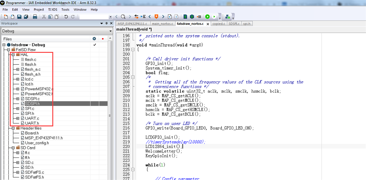
    First, customer looped drivers file into the project show as below, it also can be debug and set break point.

    Second, even the engineer keep the spi at 400k hz in SDSPI_initialize() function, the code still would be goes into 

    if (fresult) {
    // Display_printf(display, 0, 0,
    // "Error getting the free cluster count from the FatFs object");
    while (1);
    }

    Attached the define file for your information.

    New folder.7z

  • thank you Michael.  I will work to get this working on the launchpad and the SD card booster pack.  Once I get this working I will send you the project file.

    Regards,

    Chris

  • Michael,

        I was able to run the example and get successful results.  

    Attached is the project with modification for the 40Mhz MCLK, 10MHz SMCLK, and SPI on A2 (CS: P3.0, CLK: P3.1, MOSI: P3.3, MISO: P3.2).

    Regards,

    Chris

    fatSD.zip

  • Thanks Chris,

    I follow your project and found the problem with customer HW engineer.

    it caused by SPI enable pin, there is a 2.2uf CAP, made a long time from 3.3v to 0V.

    By the way, we tested the spi clock.


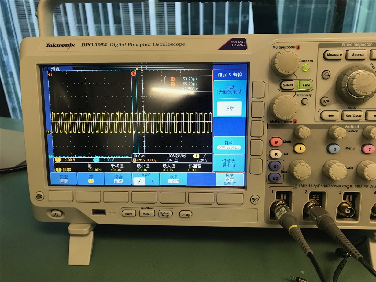
    When I used .initialPerfLevel = 4, the spi clock is 400k hz

    When I config initialPerfLevel = 5, the spi clock is 300k hz.

    What's your testing result?

    why the spi is not 2.5M HZ showed in SDSPI.C comments?

    /*
    * SPI is initially set to 400 kHz to perform SD initialization. This is
    * is done to ensure compatibility with older SD cards. Once the card has
    * been initialized (in SPI mode) the SPI peripheral will be closed &
    * reopened at 2.5 MHz.
    */

  • Hello Michael,

    Do you still need help on this topic?

    Thanks,

    Sai

  • Sai,

    No, many thanks for your help on this thread~

**Attention** This is a public forum