This thread has been locked.

If you have a related question, please click the "Ask a related question" button in the top right corner. The newly created question will be automatically linked to this question.

MSP-EXP430FR6989: How to use the ESI modul of the launchpad?

Part Number: MSP-EXP430FR6989
Other Parts Discussed in Thread: FLOWESI-GUI, MSPWARE, MSP430FR6989, EVM430-FR6989

Hi all!

I am working on a water meter and I would like to achive rotation detection / read rotation disk. I would like to count the amount of rotationd it did, and the current position of the disk.

I tried to use the ESI modul of the 6989 launchpad, with the FLOWESI-GUI generated code. I have a hard time getting started.

Is there any example code, that helps getting started/ any turorial video?

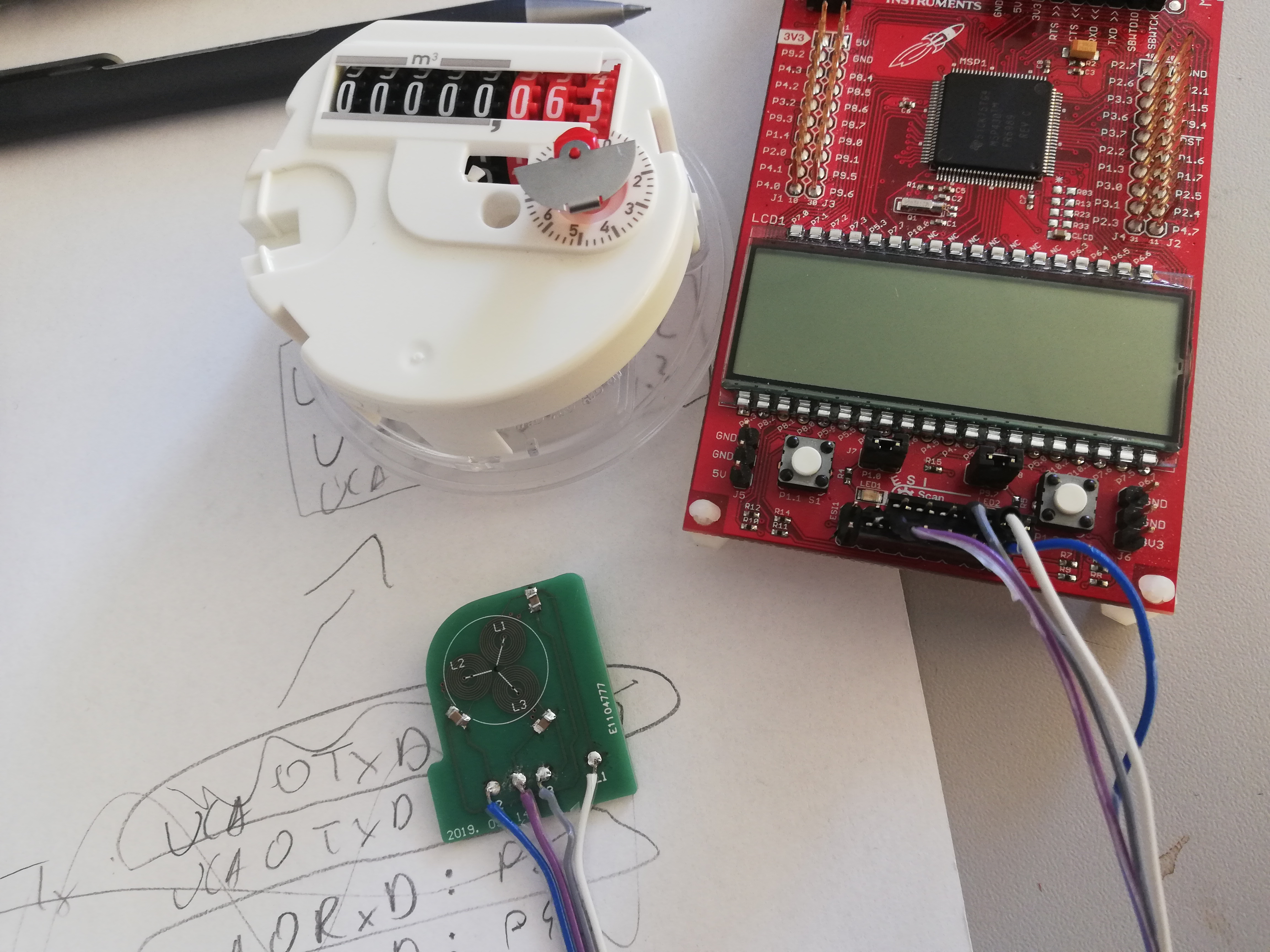
I am using 6989 launchpad with a 3 LC sensor, the sensors are 120 degrees apart. I am attaching a picture of my hardware setup.

  • Also, when I use the FLOWESI - GUI, in the toolconfig, CUSTOM_BOARD.xml it says "<!-- Valid GPIOPin values are GPIO_PIN1-GPIO_PIN8. -->", but I think its pin0 - pin7, can someone confirm this?

  • Hi Balint,

    There is an EVM board for MSP430-FR6989. It can help you on the meter design. http://www.ti.com/tool/EVM430-FR6989

    Best regards,

    Cash Hao

  • Hi Cash,

    I do not own this board, and I would like to continue the development without this board. Is it possible to do so? 

    If yes, can you tell me some starting points? I have a hard time understanding the FLOWESI-GUI.

  • First, I would like to see an oscillation signal on one of the coils. To be honest, I am not sure what values should I set in the registers to achieve that. I checked msp430fr69xx_esi_01.c in the mspware but I couldnt figure it out.

    Any help is much appreciated(even documents,videos etc).

  • Hi Balint,

    Have you ever read this application note? 

    You can start with this code, and I donot think it is neccessary to understand the FLOWESI-GUI. You can run this application following this artical without the GUI.

    Best regards,

    Cash Hao

  • Hi Cash Hao,

    I studied this document. I would like to ask a few questions.

    In this part, when the runtime calibration is discussed, I dont understand how did the "5 samples in one eighth of a rotation" comes into the picture, I would like to determine the number of  samples for my device.

    Maximum rotation: This device can work at a maximum of 3.125 cubic meter per hour(3125 impulses per hour), therefore: I get 0.868 rotation/sec ( maximum value).

    Angle of smaller portion: Half metal, half plastic, so its 180 degrees.

    Angle of sensor pair: 120 degrees. ( I have 3 sensors, each 120 degrees apart) 

    Number of samples per rotation (calculated with the given formula): 12

    Sampling rate for normal operation (calculated with the given formula): 10.416 Hz

    Runtime recalibration part:

    Time for recalibration: 9.216 sec

    I dont know "number of samples" variable, therefore I cannot calculate the sampling rate.

    My second question:

    Section 4.5 Auto-TSM Calibration

    This part contains initial settings for TSM registers. After applying this code I thought I would achieve this:

    Instead, I got this on the oscilloscope:

    How can I achieve the damping function(not the transient)?

    I can link my whole code if necessary.

    Thank you very mch for your help.

    Bálint

  • Hi Balint,

    1. It means in recalibration mode you will need five times sampling rate than in run mode. If you got 10.416Hz in run mode, you will need at least 5*10.416Hz = 52.08Hz at least in recalibration mode.

    2. The oscillation signal should have a VCC/2 offset. You need to set you scale of CH1 to 500mV or 1V and reset your trigger settings to find the real signal. If you still can not find it, we will need to look into your code then.

    Best regards,

    Cash Hao

  • Hi Cash Hao,

    I managed to solve a few problems, but I couldnt get the desired signal. It seems that if I try ESIVMIDEN=1, I get the full AVcc, not AVcc/2 as shown on  this figure:

    This is my code:

    CECTL3 |= 0x0;

    ESITSM = 0x1400; // start trigger: ACLK; TSM repeat mode=1;

    ESIAFE &= ~(ESISH);
    ESIAFE |= (ESIVMIDEN + ESITEN);

    ESITSM0 = 0x4C08;// ESIEX=1;ESILCEN=0; 10 period
    ESITSM1 = 0x4C0C;// ESIEX=1;ESILCEN=1; 10 period 
    ESITSM2 = 0xFC04;// ESIEX=0;ESILCEN=1; 32 period
    ESITSM3 = 0x0200;// stop 1 period

    ESICTL |= (ESIEN);

    this is what i get:

  • Hi,

    Have you followed the example code in the application note I shared before? You can download it in the abstract of that artical.

    Best regards,

    Cash Hao

  • Dear Cash Hao,

    sorry for the late response.

    That example code is not working for me.

    In targetConfigs folder, there is MSP430FR6989.ccxml file. This file contains this code:

    <?xml version="1.0" encoding="UTF-8" standalone="no"?>
    <configurations XML_version="1.2" id="configurations_0">


    <configuration XML_version="1.2" id="TI MSP430 USB1_0">
    <instance XML_version="1.2" desc="TI MSP430 USB1_0" href="connections/TIMSP430-USB.xml" id="TI MSP430 USB1_0" xml="TIMSP430-USB.xml" xmlpath="connections"/>
    <connection XML_version="1.2" id="TI MSP430 USB1_0">
    <instance XML_version="1.2" href="drivers/MSP430FR6989_emu.xml" id="drivers" xml="MSP430FR6989_emu.xml" xmlpath="drivers"/>
    <platform XML_version="1.2" id="platform_0">
    <instance XML_version="1.2" desc="MSP430FR6989_0" href="devices/MSP430FR6989.xml" id="MSP430FR6989_0" xml="MSP430FR6989.xml" xmlpath="devices"/>
    </platform>
    </connection>
    </configuration>
    </configurations>

    I do not have the highlighted file, nor I managed to find it. Can you help me with that?

    Also, I bought the EVM430-FR6989 board. I used the flowesi gui and code was working for me for 2 LC sensor. When I try to do 3LC test, one of the sensor doesnt receive the signal. Can you give some advice about it? (I connected all 3 sensors in the flowesi gui).

  • Hi,

    Use the attached file to replace the MSP430FR6989.ccxml file.

    Usually, when using 3 LC sensors, 2 LC sensors are used for counting, one LC is for calibration. The calibration frequency is low, so you might not be able to observe the signal. It might related to your issue.

    MSP430FR6989.ccxml

  • Dear Cash Hao,

    this ccxml file solved my problem. Thank you very much for your patience and help.

**Attention** This is a public forum