This thread has been locked.

If you have a related question, please click the "Ask a related question" button in the top right corner. The newly created question will be automatically linked to this question.

CCS/MSP430FR2355: problem with UART communication

Part Number: MSP430FR2355

Tool/software: Code Composer Studio

Hello,

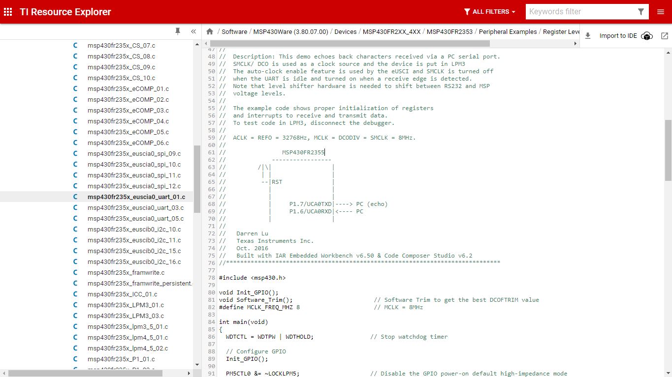
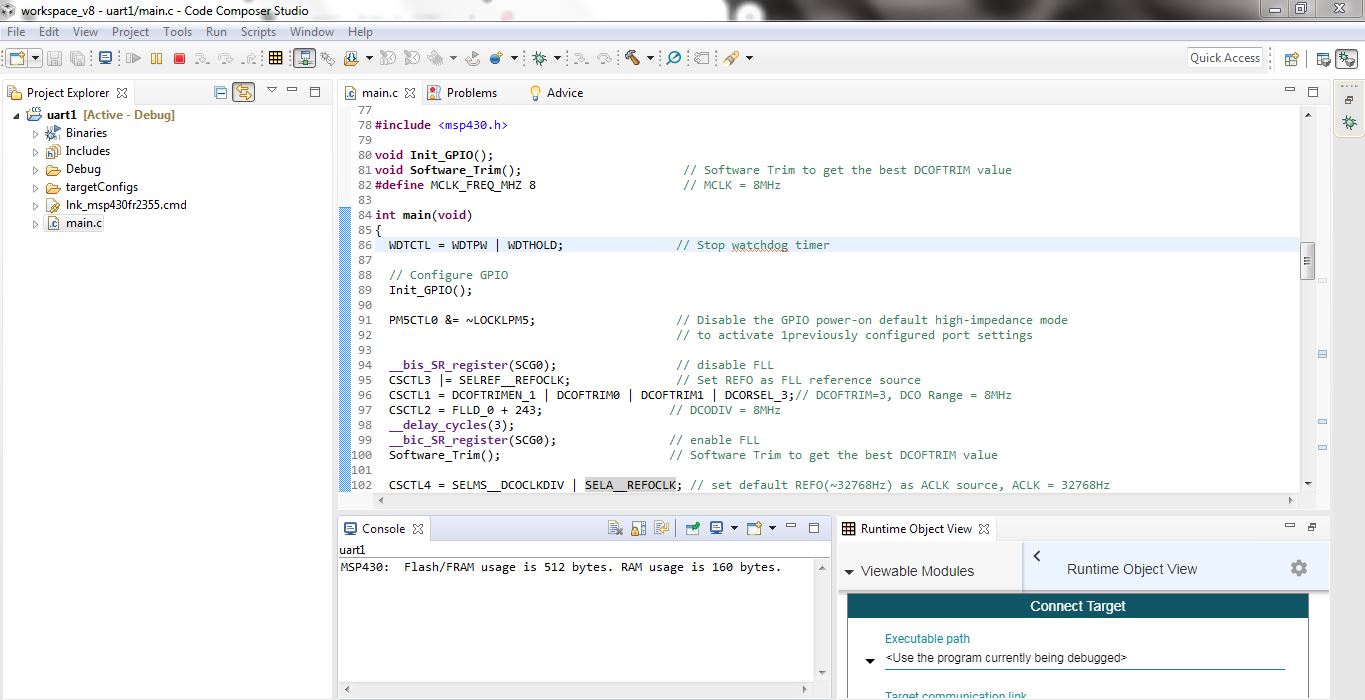
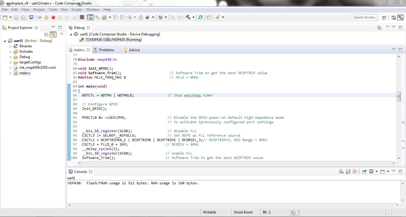
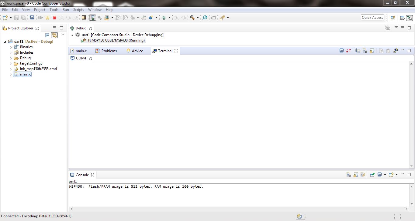
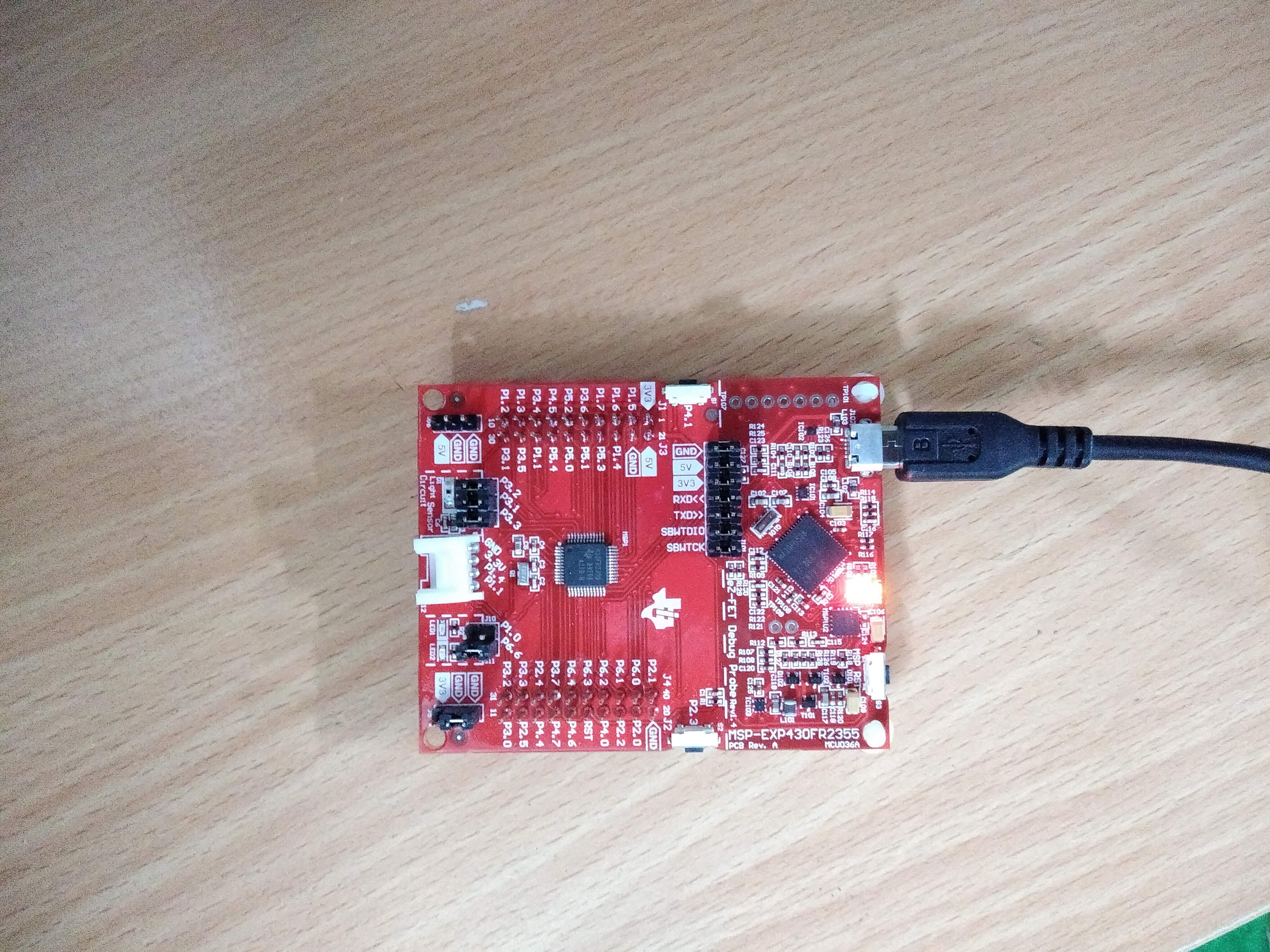
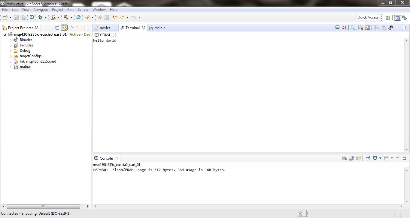
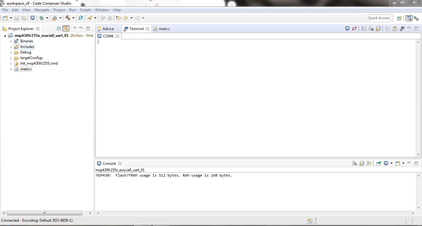
I am trying to connect MSP430FR2355 with my PC through UART communication to echo characters entered by me through keyboard. I copied example code msp430fr235x_euscia0_uart_01.c from TI resource explorer to CCS v8 on my PC. As given in description,I should get echo of characters entered by me on CCS terminal but this is not working for me. Cursor is blinking but I am unable to enter any character on terminal.

Regards

Sourav Prasad

  • Per the Launchpad data sheet (SLAU680) Sec 2.2.4, the backchannel UART is connected to UCA1, and this Example talks to UCA0. (This does seem like an oversight.)

    Probably the simplest remedy is to jumper the P1.6/P1.7 pins on J1 to the RXD/TXD (repectively) pins on the USB side of J101 ("bridge header"). (You'll have to remove the J101 jumpers, of course.)

    Alternatively, change all the UCA0 references to UCA1, and the line which sets P1SEL0.6/7 to set instead P4SEL0.2/3 [Ref data sheet (SLASEC4B) Table 6-66.]

  • Hi Bruce,

    The first method(jumper P1.6/P1.7 pins on J1 to the RXD/TXD)  worked properly for me for example code msp430fr235x_euscia0_uart_01.c . Characters entered by me through keyboard is appearing on CCS v_8 serial terminal configured at baudrate 9600. I am sharing image for first method.

    But the second method didn't work. To configure backchannel UART(UCA1) I changed all UCA0 and P1SEL0.6/7 references in example code to UCA1 and P4SEL0.2/3 respectively.

    #include <msp430.h>
    
    void Init_GPIO();
    void Software_Trim();                       // Software Trim to get the best DCOFTRIM value
    #define MCLK_FREQ_MHZ 8                     // MCLK = 8MHz
    
    int main(void)
    {
      WDTCTL = WDTPW | WDTHOLD;                // Stop watchdog timer
    
      // Configure GPIO
      Init_GPIO();
    
      PM5CTL0 &= ~LOCKLPM5;                    // Disable the GPIO power-on default high-impedance mode
                                               // to activate 1previously configured port settings
    
      __bis_SR_register(SCG0);                 // disable FLL
      CSCTL3 |= SELREF__REFOCLK;               // Set REFO as FLL reference source
      CSCTL1 = DCOFTRIMEN_1 | DCOFTRIM0 | DCOFTRIM1 | DCORSEL_3;// DCOFTRIM=3, DCO Range = 8MHz
      CSCTL2 = FLLD_0 + 243;                  // DCODIV = 8MHz
      __delay_cycles(3);
      __bic_SR_register(SCG0);                // enable FLL
      Software_Trim();                        // Software Trim to get the best DCOFTRIM value
    
      CSCTL4 = SELMS__DCOCLKDIV | SELA__REFOCLK; // set default REFO(~32768Hz) as ACLK source, ACLK = 32768Hz
                                               // default DCODIV as MCLK and SMCLK source
    
      // Configure UART pins
      P4SEL0 |= BIT2 | BIT3;                    // set 2-UART pin as second function
    
      // Configure UART
      UCA1CTLW0 |= UCSWRST;
      UCA1CTLW0 |= UCSSEL__SMCLK;
    
      // Baud Rate calculation
      // 8000000/(16*9600) = 52.083
      // Fractional portion = 0.083
      // User's Guide Table 17-4: UCBRSx = 0x49
      // UCBRFx = int ( (52.083-52)*16) = 1
      UCA1BR0 = 52;                             // 8000000/16/9600
      UCA1BR1 = 0x00;
      UCA1MCTLW = 0x4900 | UCOS16 | UCBRF_1;
    
      UCA1CTLW0 &= ~UCSWRST;                    // Initialize eUSCI
      UCA1IE |= UCRXIE;                         // Enable USCI_A0 RX interrupt
    
      __bis_SR_register(LPM3_bits|GIE);         // Enter LPM3, interrupts enabled
      __no_operation();                         // For debugger
    }
    
    void Software_Trim()
    {
        unsigned int oldDcoTap = 0xffff;
        unsigned int newDcoTap = 0xffff;
        unsigned int newDcoDelta = 0xffff;
        unsigned int bestDcoDelta = 0xffff;
        unsigned int csCtl0Copy = 0;
        unsigned int csCtl1Copy = 0;
        unsigned int csCtl0Read = 0;
        unsigned int csCtl1Read = 0;
        unsigned int dcoFreqTrim = 3;
        unsigned char endLoop = 0;
    
        do
        {
            CSCTL0 = 0x100;                         // DCO Tap = 256
            do
            {
                CSCTL7 &= ~DCOFFG;                  // Clear DCO fault flag
            }while (CSCTL7 & DCOFFG);               // Test DCO fault flag
    
            __delay_cycles((unsigned int)3000 * MCLK_FREQ_MHZ);// Wait FLL lock status (FLLUNLOCK) to be stable
                                                               // Suggest to wait 24 cycles of divided FLL reference clock
            while((CSCTL7 & (FLLUNLOCK0 | FLLUNLOCK1)) && ((CSCTL7 & DCOFFG) == 0));
    
            csCtl0Read = CSCTL0;                   // Read CSCTL0
            csCtl1Read = CSCTL1;                   // Read CSCTL1
    
            oldDcoTap = newDcoTap;                 // Record DCOTAP value of last time
            newDcoTap = csCtl0Read & 0x01ff;       // Get DCOTAP value of this time
            dcoFreqTrim = (csCtl1Read & 0x0070)>>4;// Get DCOFTRIM value
    
            if(newDcoTap < 256)                    // DCOTAP < 256
            {
                newDcoDelta = 256 - newDcoTap;     // Delta value between DCPTAP and 256
                if((oldDcoTap != 0xffff) && (oldDcoTap >= 256)) // DCOTAP cross 256
                    endLoop = 1;                   // Stop while loop
                else
                {
                    dcoFreqTrim--;
                    CSCTL1 = (csCtl1Read & (~DCOFTRIM)) | (dcoFreqTrim<<4);
                }
            }
            else                                   // DCOTAP >= 256
            {
                newDcoDelta = newDcoTap - 256;     // Delta value between DCPTAP and 256
                if(oldDcoTap < 256)                // DCOTAP cross 256
                    endLoop = 1;                   // Stop while loop
                else
                {
                    dcoFreqTrim++;
                    CSCTL1 = (csCtl1Read & (~DCOFTRIM)) | (dcoFreqTrim<<4);
                }
            }
    
            if(newDcoDelta < bestDcoDelta)         // Record DCOTAP closest to 256
            {
                csCtl0Copy = csCtl0Read;
                csCtl1Copy = csCtl1Read;
                bestDcoDelta = newDcoDelta;
            }
    
        }while(endLoop == 0);                      // Poll until endLoop == 1
    
        CSCTL0 = csCtl0Copy;                       // Reload locked DCOTAP
        CSCTL1 = csCtl1Copy;                       // Reload locked DCOFTRIM
        while(CSCTL7 & (FLLUNLOCK0 | FLLUNLOCK1)); // Poll until FLL is locked
    }
    
    
    #if defined(__TI_COMPILER_VERSION__) || defined(__IAR_SYSTEMS_ICC__)
    #pragma vector=USCI_A0_VECTOR
    __interrupt void USCI_A0_ISR(void)
    #elif defined(__GNUC__)
    void __attribute__ ((interrupt(USCI_A0_VECTOR))) USCI_A0_ISR (void)
    #else
    #error Compiler not supported!
    #endif
    {
      switch(__even_in_range(UCA1IV,USCI_UART_UCTXCPTIFG))
      {
        case USCI_NONE: break;
        case USCI_UART_UCRXIFG:
          while(!(UCA1IFG&UCTXIFG));
          UCA1TXBUF = UCA1RXBUF;
          __no_operation();
          break;
        case USCI_UART_UCTXIFG: break;
        case USCI_UART_UCSTTIFG: break;
        case USCI_UART_UCTXCPTIFG: break;
        default: break;
      }
    }
    
    void Init_GPIO()
    {
        P1DIR = 0xFF; P2DIR = 0xFF;
        P1REN = 0xFF; P2REN = 0xFF;
        P1OUT = 0x00; P2OUT = 0x00;
    }


    this code is not working for backchannel UART (UCA1). Please help me to configure backchannel UART.


    Regards
    Sourav Prasad
  • > #pragma vector=USCI_A0_VECTOR

    This is actually also a reference to UCA0. Try:

    > #pragma vector=USCI_A1_VECTOR


  • Thank you Bruce. Finally it worked perfectly.

**Attention** This is a public forum