This thread has been locked.

If you have a related question, please click the "Ask a related question" button in the top right corner. The newly created question will be automatically linked to this question.

MSP430FR6043: USS the amplitude of ADC Capture is negative

Part Number: MSP430FR6043

Dear team,

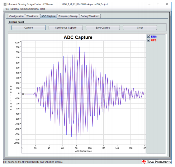
I am using the USS of MSP430FR6043. I found that the amplitude of ADC Capture has negative number in Ultrasonic Design Center. 

So please kindly tell me why it has negative number.

http://www.ti.com.cn/cn/lit/ml/slau765b/slau765b.pdf  

Figure 6. ADC Capture in Design Center

  • Hello Susan,

    the conversion result is a signed integer number that can range from -2048...+2047. Its zero-reference is at the bias voltage that is generated inside the 'FR6047. The Bias voltage is electrically decoupled using a 1nF capacitor at each analog input terminal. Since we are only interested in AC amplitudes the exact bias voltage (~750mV) is not of interest. Using singed numbers is mathematically much easier.  it's that simple.  

    The first ADCs that came out had positive and negative supply voltage and operated with signed numbers already.... later when the first single supply ADC came out unsigned numbers were used. Some felt it is more convenient and it reflects the single supply feature...   after all its just a convention....

    Oh!, we typically use an 3dB amplitude margin in the above case... therefore staying within +/- 1000 is a good capture signal.

    have a nice day

        Johann Zippperer


  • Thanks for your reply!

    So it means  if i want to collect the +- signal of the transducer, i need to use the external circuit to raise the original signal too high and raise the 0 value of the signal to the bias voltage. Is this true?

    Is the offset register register PGABIAS? There is also a bias of 750mv, what is the input voltage range of the USS acquisition?

  • Hello again Susan,

    yes, this is usually done with one resistor and on cap as shown in the UG.

    The below pictures are taken from the UG; The one just below shows the situation before the sonic pulse train arrives on CH1. The CH1_OUT terminal provides 0V/GND while CH1_IN terminal provides RxBias (which has the value of PgBias) via the switch. This charges up the coupling cap. But is also shorts the input of the input multiplexer to RxBias (no signal would be received at that moment).

    Some microseconds before the acoustic signal is arriving the bias switch is opened; thus allowing the multiplexer to pick up the incoming pulse train. The coupling cap will hold the RxBias value long enough to provide the required DC-offset from ground...

    what is shown in the drawings is just the DC content of the signal...

    have a nice day

        Johann

**Attention** This is a public forum