This thread has been locked.

If you have a related question, please click the "Ask a related question" button in the top right corner. The newly created question will be automatically linked to this question.

MSP430AFE253: MSP430AFE253 reset issue

Part Number: MSP430AFE253

Dear TI Team,

We have a design which uses  MSP430AFE253. But we encountered a strange POR reset issue as the MCU occasionally failed to properly reset itself , thus prevents it from running firmware application. However, when we physically shorted RST pin to ground as soon as we observed MCU reset failure, the MCU resumes working again. I included below information for you reference. Would you please kindly review our design and check if there is any potential cause to the reset issue that we have been experiencing? Thank very much for your help.  


1)  Figure 1 -schematic design,

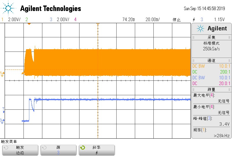
2) Figure 2 - Waveform capture for MCU_VCC/RST pins

3) Figure 3  - Waveform capture for crystal output.        

4) Crystal data sheet

Best regards,

Peter

Figure 1: MSP430AFE253 Schematic

Figure2 : Scope Capture - MCU-VCC (Orange color) / MCU-RST (Blue color)

Figure 3: Crystal output (Orange Color)

crystal.pdf

  • Hello,

    What is the 2nd dip in the VCC line?  This is a capture of when the device doesn't work?  

    This seems like a BOR issue of some sort.  The initial VCC ramp looks to be clean and fast enough.  The immediate dip in VCC looks like it's probably going to cause issues.  

    Figure 5-12 shows the device behavior as VCC ramps and dips.  This dip is likely not going low enough to trigger a BOR and reset the device, which is show as V(B_IT-) in table 5.14.  

    You could try to immediately enable the SVS to monitor the voltage and put the device in reset properly through this dip. 

    Thanks,

    JD

  • Hi JD,

    Thanks for your support.

    The 2nd dip can he captured every time when the device power on. Sometime, it doesn't work.

    I need your help with some questions about BOR.

    1) What's td(BOR) 2000us in table 5.14 ?

    2) In table 5.14, the BOR trigger point is 1.42V. Does it mean the device will generate a BOR reset when the VCC line level is below the 1.42V ? 

         If the VCC line dip to the range 1.42V~1.54V, and then the VCC line return to the normal level, does it can generate a POR reset, like my issue which has been proposed by Peter?

    3) About SVS, where is the apllication note and example code?

    Best Regards,

    Yihong.

  • Hi JD,

    Add two questions, thank you.

    4) How much time bettween the device power on and the device start to run the user code?

    5) Dose there have some requirements for external oscilator before the device start to run the user code, such as the external oscilator must be keeping stable?

  • Hello Yihong,

    1. Td(BOR) is a typical time between the BOR hitting the Vhys point and releasing the POR.  This can be seen more clearly on Figure 5-12.  

    2.  Yes, the device will not generate a POR from the BOR until it's below this V(B_IT) which is 1.42V Typical.  This is just a typical value but will vary a bit from device to device.  This is where the SVS should be used to catch it earlier.  Again, see Figure 5-12

    3.  There are some SVS examples in the code examples zip here: http://www.ti.com/product/MSP430AFE253/toolssoftware#softTools

    4. CPU starts running after Td(BOR).  This is specified in note #2 under the BOR table 5.14

    5. Yes, the oscillator should be stable.  VCC must also remain above VCC(min) which is the minimum supply for the desired operating frequency.  These VCC ranges are defined in Table 5.3 and Figure 5-1.  

    Thanks,

    JD

**Attention** This is a public forum