This thread has been locked.

If you have a related question, please click the "Ask a related question" button in the top right corner. The newly created question will be automatically linked to this question.

CCS/MSP-FET: MSP430: Error connecting to the target: Unknown device

Part Number: MSP-FET
Other Parts Discussed in Thread: MSP430G2553,

Tool/software: Code Composer Studio

Hello!

I have a problem flashing my MSP430G2553 on a custom board. When I try to flash a simple program, the red LED of the debugger blinks 5 times, while the green LED is on constantly, and then both LEDs stay on and I get the error message: "MSP430: Error connecting to the target: Unknown device"

I connected the MSP-FET debugger directly to my Ubuntu 18.04 machine. Connected to the debugger, there is the MSP-FET-432ADPTR adapter board. I use a custom cable (approximately 25 cm long - can this be the issue?) with 10 pins connected to the J2 connector on the adapter board. On the cable, I added a 46k Ohm resistor between RST and Vcc. At first I also added a 1nF Capacitor between RST and Ground, but then I removed it, after I recognized that in the data sheet the Capacitor actually is a MAXIMUM value, not a recommended one. Nevertheless, adding or removing the Cap didn't change anything.

I am using Code Composer Studio Version 9.2.0.00013, and I try to upload this simple program:

#include <msp430g2553.h>

/**
 * main.c
 */
int main(void)
{
	WDTCTL = WDTPW | WDTHOLD;	// stop watchdog timer
	while(1) {;}
	return 0;
}

All settings in CCS should be the default settings.

The following picture illustrates the connections between the debugger / adapter board and the microcontroller:

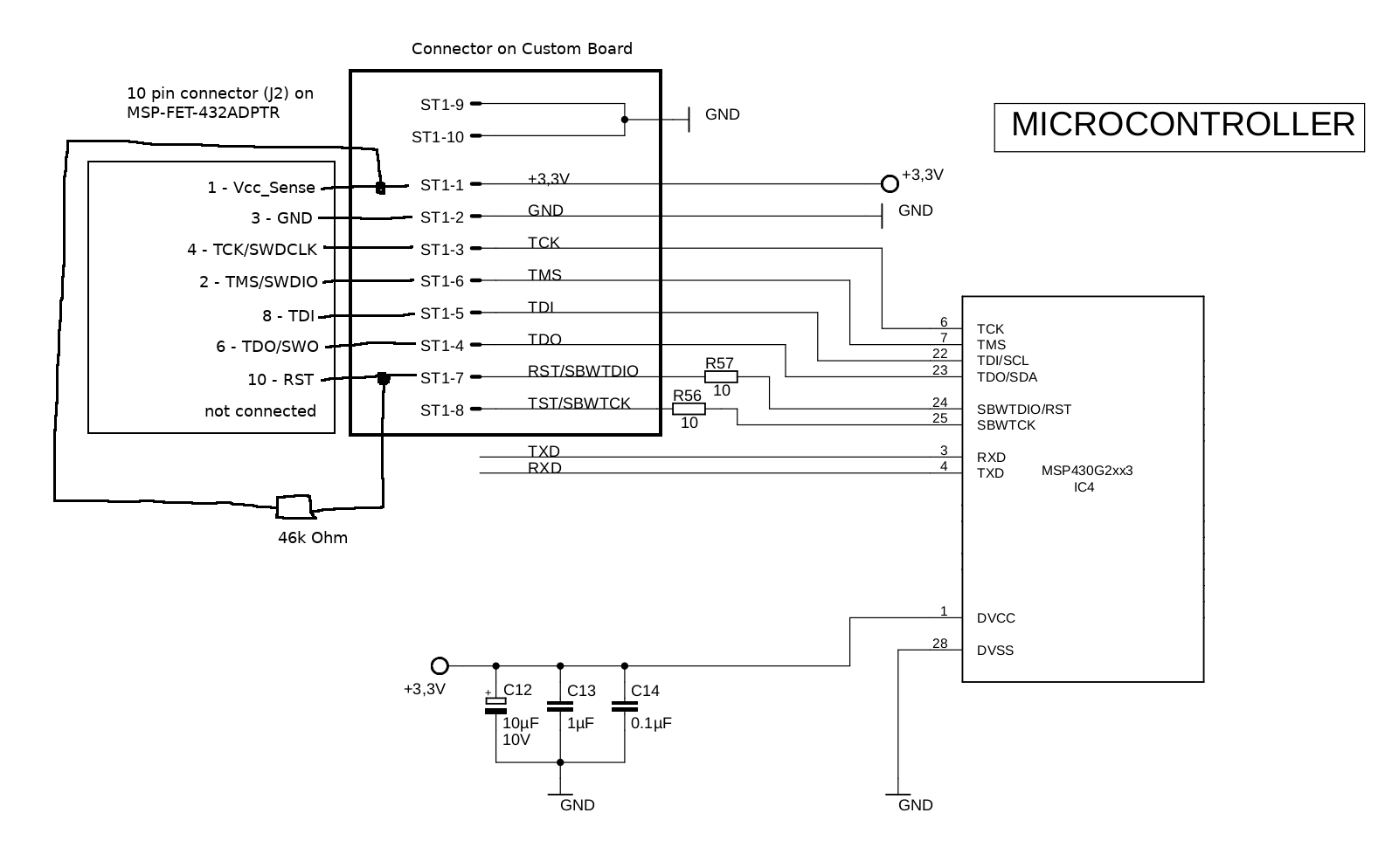
The Controller is externally powered with 3.3V, and the switch on the adapter board is set to the left (to enable Vcc_Sense).

Please tell me, if I made any mistakes with the connections. Any help is appreciated!
I try to improve the connection cable and make it shorter. It would be great if I can catch any other mistake early and correct the connection with the new cable.

  • Hello Max,

    Please refer to figure 2-1 of the hardware tools user guide shows the 4 wire JTAG connections required: http://www.ti.com/lit/ug/slau278ae/slau278ae.pdf 

    To make sure I understand your setup, you have an MSP-FET, connected to the adaptor board, then another 25 cm cable connected to the board?  That does seem really long and could for sure be causing issues.  Typically, we recommend keeping the cable <8 inches in total length.   

    The biggest thing I see missing is a capacitor on the RST line, so please add that.  I would also try shortening the cable. 

    Why are you using the adaptor board if you have a custom connector? 

    Thanks,

    JD  

  • Many thanks for your answer! I will try this and then report back.

    I already knew the figure 2-1. What I understood so far was, that C1 rather is the "upper limit", as it says in the text to figure 2-1 (E). So is C1 really necessary and should I add it? What size of C1 should I add for a MSP430G2553? Is 1.0 nF fine?

  • So I shortened the cable to 8 cm, and I added a capacitor of 1 nF between RST and GND. However, the same error still occurs, even after retrying several times. I also connected the debugger to every usb port on my machine, still the same error.

    Now I have no idea what I could do to get it working. What value for the capacitor would you suggest?

  • Hey Max,

    The Cap on RST is critical to have.  I would recommend 2.2nF.  

    Due to the cable length, you could also try slowing down the JTAG communication.  In Code Composer target configuration file, you can change the JTAG.SBW speed.  Trying running in slow mode.    

    Do you have any other boards to best the programmer with?  

    Thanks,

    JD

  • Hi JD,

    thanks for your help! However, it turns out that for the MSP430G2553 (and generally the 430G2xxx family I think), the JTAG pins are multiplexed. Therefore I have to connect the TEST pin to the debugger. Since the adapter board is for MSP432 devices, as the name says, and they have no multiplexed JTAG pins, the TEST pin is not available on any of the connectors on the adapter boards. That is why I didn't connect the TEST pin previously. Please don't ask, why I used this setup.

    When I connect the TEST pin to the board (+ I shortened the cable a lot, but I don't know if this was necessary), flashing via JTAG works now! I didn't add a capacitor, so it seems the 2.2nF are not really necessary.

    So this solved my issue, and hopefully helps others who forgot to connect the TEST pin.

  • Actually, now I found out what for I need the Cap: When disconnecting the Debugger, the microcontroller resets itself continuously. I added a 1nF (I didn't have a 2.2nF at hand) between RST and GND, and this solved the issue now completely.

    Curiously enough, the cable itself (although it is very short) has a high enough intrinsic capacitance that the additional Cap is not necessary. Because when I leave the cable on the board and only disconnect the Debugger, the board works fine.

    Anyways, thanks for your help! Now I solved this issue completely :)

**Attention** This is a public forum