This thread has been locked.

If you have a related question, please click the "Ask a related question" button in the top right corner. The newly created question will be automatically linked to this question.

CCS: MSP430FR5887 Non-magnetic sensor

Tool/software: Code Composer Studio

With ESI as the non-magnetic sensor (L:470uH, C:220pF), some machines will lose count at a high temperature of 55 . Counting normally will also be wrong after a period of time. Is there any requirement for LC, such as the consistency of inductance value

  • Hello,

    I'll need to check with our ESI team and get back to you. The recent holidays may delay their response, so we appreciate your patience.

    In the meantime, please check that the ESI2 errata is not causing this behavior. Also, when you mention the consistency of the inductance value, are there multiple sensors in the same system or are the inductor variations across each system? What's the expected variation?

    Also, Section 37.2.1.7 Optional Comparator Offset Cancellation in the MSP430FR58xx, MSP430FR59xx, and MSP430FR6xx Family User's Guide mentions the following:

    The ESI's comparator has an offset that drifts over temperature and supply voltage. For some applications the specified offset error and offset drift may be acceptable - see device-specific data sheet. If the offset error is not acceptable, adding a comparator autozero cycle within the TSM sequence can minimize the offset error. After the inserted autozero TSM cycle, the comparator operates effectively with a zeroed offset.

    I suspect that this has something to do with the count loss as the temperature increases.

    Regards,

    James

  • hello,

            I'm glad to hear from you,Here's the situation.The sensor has three inductors, each of which will have a different value. If the difference is large (10uH), the high temperature count will be inaccurate.You said ESI2 errata I saw is the possibility, but where can I download the device - specific data shee, and Optional Comparator Offset Cancellation sample program

  • Hello,

    Would you be able to share your schematics? If so, please don't post them here in case they are proprietary but instead, request my friendship and after I accept, you'll be able to send them to me privately. Our ESI team will be available on Thursday, so the schematic will help them in this investigation.

    Thanks,

    James

  • I don't know why, my email can't go out

  • hello,

         When will you know the result.I'm in a hurry here.

    thanks

  • Hello,

    I'm sorry about the delay. I will ping that team for an update and let you know early next week.

    Regards,

    James

  • Hi, Hello, my name is Johann, working out of Germany... 1st day back in office, sorry for my delay to come into this round....

    I do not expect large changes in the MSP430's device's analog behavior in the temperature range you've described.... But I expect changes in the L's and C's of the tank circuit over temperature if you've got an unlucky component selection.

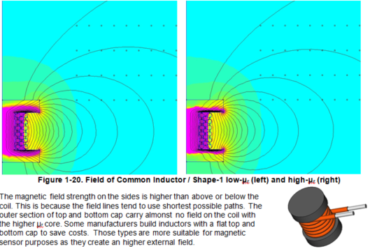
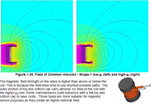
    With the ESI concept you are using the inductor as a sensor for a distortion of the magnetic field (AC-field). This by using a parasitic property of an inductor. Modern and good inductors are supposed to show little external fields to keep the interference with other components low. Then it depends if the inductor was designed as storage inductor for an SMPS or as filter inductor to reduce AC- noise etc.

    Some hints for the L: avoid Iron cores (full metal cores), avoid metal powder cores, avoid high permeable cores...

    Some hints for the C: avoid PZT based dielectrics

    Could you check if your L-C circuit changes it's resonance frequency over temperature; just the L and C soldered together; nothing else attached. This can be done with an absorption frequency meter (dip-meter). Those meters are simple meters that exist for many decades already. In out lab we have some laying around from the 70's 80's of last millennium. Sometimes they are used => this would be such a case...

    Alternatively you can take a scope snapshot on an cold and hot tank circuit.

    The ESI checks for a voltage level at an given moment in time. If a certain level is reached or not is an indication that the magnetic field is distorted by an metal piece or not. That's basically how the physical mechanism works.

    In case you can tear apart one of your Ls, please let me know hoe many windings if has; mine has 160...   This number allows me to calculate the AL-value which again allows to estimate the temp behavior of the material....

    have a nice day

          Johann


  • Hello,Johann

        Sorry I'm late. It's Chinese New Year.

        I'll try it your way.               

        mine has 160...(Do you have 160 laps of inductance?) Have you sent any photos to see? how many uH? Mine is 470uH and 220pF)

  • Hello,Johann

         Can you provide a brand and model of inductance that you think is ok, so that we can continue the experiment.

    thanks

  • Hi,

    I cannot propose a specific brand, but I can explain how I would select a coil that is suitable.

    The inductance of a coil is influences by the # of turns and the AL-value of the core. The equation is : L=AL*n^2.

    n are the # of turns ; AL is usually given in nHy. it is determines by the for of the core and the the material property "u_r".

    The "u_r"-value of the core influences how the magnetic field is formed by the coil; it also influences the inductance as shown above.

    As you can see above high "u_r" ties the fiels into the core. But we do not want this because wee need an external field to sense the presence of an metal.

    Therefore a coil with low "AL" id better.

    If you have a coil with 160 turns to get to 470uHy  => "AL"=470u/160^2=18.35nHy.

    A coil that only has 50 turns has an "AL" of 188nHy  => here the first coil is better since a larger external field can be expected.

    The other way to test is is simulating the geometry of simply measuring it. Here the "Dip-Meter" is helpful. You can see the impact of the "Dip" in dependency of the distance of the tans circuit.

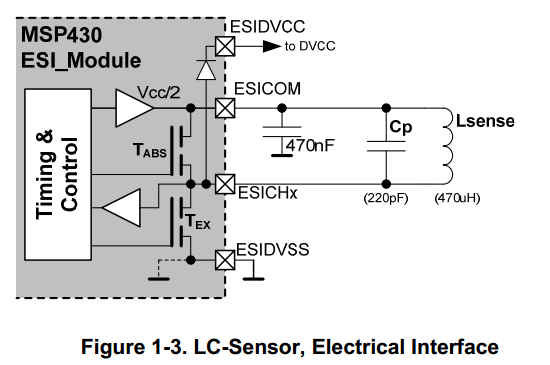
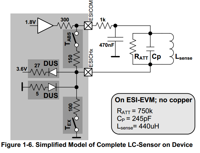
  • So it seems that the current inductive material used is no problem.Should I change the circuit? My circuit looks like figure 1-3, ESIVDCC=3V.I want him to use it for 16 years. Should I change it to figure 1-6?Should I change the parameters of LC?

  • Hello again,

    The Figure 1-6 is representing a analog behavioral model.

    Here it means:

       - the internal equivalent resistor for switches and diodes are as given in the dark grey boxes

       - the source resistance of ESICOM is 300 Ohms

       - the observed attenuation on the tank circuit behaves as if a || resistor of 750k would be connected...

         (in reality this resistor does not exist; the loss comes from the parasitic pin capacitance that did not get modelled in this simplified approach)

    On thing however could be added for higher reliability this is the 1k resistor from ESICOM to the 470nF cap.

    This is why.

    All is ok as long the PCB traces between the 470nF cap from its ground terminal to the ESICOM terminal is short. If for some reason (unlucky placing) Lsense does a magnetic coupling into the loop generated by the lead traces of the 470nF cap; Then  a longer settling time on ESICOM is caused. This can be reduced by the shown 1k resistor. The ESICOM ouput is a DC-controlled. 

    No worries the output is stable with this resistor. We even tried to  form the ground lead of the 470nF cap as 5 secondary windings on to of Lsense => all stable.

  • Can you say what state the inductance of the sensor should be in when these three functions are run?for example :1.2. The sensor is placed on the 180-degree metalpointer of the water meter, and the pointer does not rotate;3. The sensor is placed on the 180-degree metal pointer of the water meter and the pointer turns;Or some other state.

    TMS_Auto_cal ();

    Find_Noise_level ();

    Set_DAC ();

    I saw that in SLAA639, but I didn't quite get it.

    TMS_Auto_cal ();It doesn't say what state it's running in.

    Find_Noise_level ();What is the state of the inductance when the pointer is not moving?1. One of the inductors is above the metal and the other two are above the nonmetal;2. One of them is above the non-metal and the other two are above the metal;One of them is above the metal, the other two are at the critical point between the metal and the non-metal.

    In addition, it is stated in 1.2.3.2 of swp140528.pdf that the service life of the chip is 10. Is there any way to extend it to 15 years.

  • Since there were not further questions on this thread I will close it.

    have all a nice day

         Johann

  • … some stuff got stuck in the message cache...  issue will be addressed..   Johann

  • Since there were no further questions on this topic I am closing this thread.

    thanks  and have all a nice day

        Johann

**Attention** This is a public forum