Other Parts Discussed in Thread: ADS8910B,
We are using an MSP432E401Y to interface with a TI ADS8910B ADC, and we are trying to sample @ 1MSPS. We are using the QSSI in quad data mode with the ADS8910B. The ADC CONVST signal is connected to a PWM pin on the MSP432, running at a period of 1us. We have a hardware interrupt set at the highest priority on this PWM signal to read the data from the ADC after every conversion cycle.
We were able to get the QSSI interface working @ 500kSPS (2us PWM interval) without using DMA. With 1us sampling however, our timing becomes much more critical and we decided to use the uDMA to handle the QSSI data transfer from the ADC.
From the ADS8910B data sheet, there is a window 30ns before and 20ns after the CONVST rising edge where digital signals cannot toggle. This is the time that the ADC is sampling the input signal, and digital signals toggling during this time could couple noise onto the ongoing conversion. Due to this requirement, we need to have tight timing control over when the QSSI data transfer occurs. Please see below SSI DMA init and PWM IRQ Handler code for our current implementation:
void initSSIuDMA(void)
{
    MAP_SysCtlPeripheralEnable(SYSCTL_PERIPH_UDMA);
    MAP_uDMAEnable();

    MAP_uDMAControlBaseSet(pui8ControlTable);

    // pulled from udma_demo.c and modified for SSI2 RX only
    MAP_SSIDMAEnable(SSI2_BASE, SSI_DMA_RX | SSI_DMA_TX);

    MAP_uDMAChannelAttributeDisable(UDMA_CH12_SSI2RX,
                                    UDMA_ATTR_ALTSELECT | UDMA_ATTR_USEBURST |
                                    UDMA_ATTR_HIGH_PRIORITY |
                                    UDMA_ATTR_REQMASK);

    // enable to keep data flowing
    MAP_uDMAChannelAttributeEnable(UDMA_CH12_SSI2RX, UDMA_ATTR_USEBURST);

    MAP_uDMAChannelControlSet(UDMA_CH12_SSI2RX | UDMA_PRI_SELECT,
                              UDMA_SIZE_8 | UDMA_SRC_INC_NONE | UDMA_DST_INC_8 |
                              UDMA_ARB_1 | UDMA_NEXT_USEBURST);

    MAP_uDMAChannelTransferSet(UDMA_CH12_SSI2RX | UDMA_PRI_SELECT,
                               UDMA_MODE_BASIC,
                               (void *)(&SSI2->DR),
                               receive_data, 3);


    MAP_uDMAChannelAttributeDisable(UDMA_CH13_SSI2TX,
                                    UDMA_ATTR_ALTSELECT | UDMA_ATTR_USEBURST |
                                    UDMA_ATTR_HIGH_PRIORITY |
                                    UDMA_ATTR_REQMASK);

    // enable to keep data flowing
    MAP_uDMAChannelAttributeEnable(UDMA_CH13_SSI2TX, UDMA_ATTR_USEBURST);

    MAP_uDMAChannelControlSet(UDMA_CH13_SSI2TX | UDMA_PRI_SELECT,
                              UDMA_SIZE_8 | UDMA_SRC_INC_8 | UDMA_DST_INC_NONE |
                              UDMA_ARB_1 | UDMA_NEXT_USEBURST);

    MAP_uDMAChannelTransferSet(UDMA_CH13_SSI2TX | UDMA_PRI_SELECT,
                               UDMA_MODE_BASIC,
                               send_data,
                               (void *)(&SSI2->DR), 3);

    MAP_uDMAChannelAssign(UDMA_CH12_SSI2RX);
    MAP_uDMAChannelEnable(UDMA_CH12_SSI2RX);

    MAP_uDMAChannelAssign(UDMA_CH13_SSI2TX);
    MAP_uDMAChannelEnable(UDMA_CH13_SSI2TX);
}
Void PWM0_0_IRQHandler(UArg arg)
{
//  timing in PWM INT: 340ns
//    GPIOP->DATA |= 0x01;

    // get interrupt status
    getIntStatus = HWREG(PWM0_ADDR + PWM_O_X_ISC);

    // Clear FSSHLD to de-assert CS
    HWREG(SSI2_BASE + SSI_O_CR1) &= ~(SSI_CR1_FSSHLDFRM);

    reads[buff->writeIndex++] = ( (receive_data[2] << 16) | (receive_data[1] << 8) | (receive_data[0]) );
    // the following line is doing the if-statement code commented below. This could save 10% from 380ns to 340ns
    // Reference: swrp146 "Software Design Using the MSP432 Lecture"
    buff->writeIndex = (((( buff->size == buff->writeIndex ) << 31) >> 31) & 0) | (((!(buff->size == buff->writeIndex ) << 31) >> 31) & buff->writeIndex);
//    if(buff->writeIndex >= buff->size)
//    {
//        buff->writeIndex = 0;
//    }

    // reset DMA for next transaction
    pui8ControlTable[216] = 0x29;   // TX
    pui8ControlTable[200] = 0x29;   // RX
    HWREG(UDMA_ENASET) = 0x3000;    // re-enable both

    // clear interrupt
    HWREG(PWM0_ADDR + PWM_O_X_ISC) = getIntStatus;

    // Set FSSHLD to assert CS for entire data transfer frame
    HWREG(SSI2_BASE + SSI_O_CR1) |= SSI_CR1_FSSHLDFRM;

//    GPIOP->DATA &= ~(0x01);
}
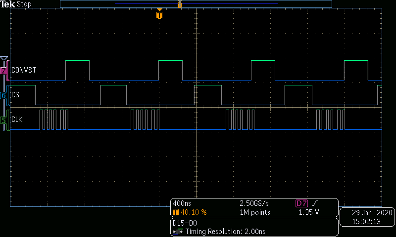
I am having trouble controlling the timing of the QSSI data transfer with the above implementation. See below scope capture for timing of QSSI signals with the above code. The QSSI data transfer happens near the end of the conversion cycle, and is toggling too close to the start of next CONVST rising edge, and thus we are violating the ADS8910B spec.
Once we reset the DMA in the PWM interrupt, the QSSI controller & DMA controller take over and complete the data transfer. I've tried moving the 3 lines of code that reset the DMA around within the interrupt, but this has not resulted in compliant timing, and in the worst case if I move the reset near the top of the interrupt handler, some of the conversion cycles do not have a data transfer occur.
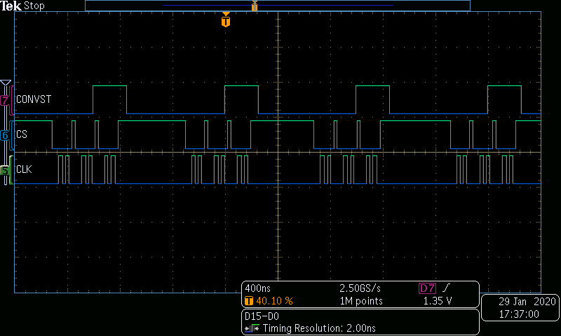
Another issue I am having is with the CS signal. We want the CS signal to assert low at the beginning of the transfer (when the CLK starts toggling) and de-assert high right after the transfer is complete. This was not a problem when we implemented the QSSI without DMA, but with DMA we have been having a hard time getting the CS to behave the way we want. With FFSHLDFRM = 1, the CS signal is constant low. With FSSHLDFRM = 0 the CS signal de-asserts between every byte that is transferred (see below capture):
The workaround we are using is to set and clear the FSSHLDFRM bit within the PWM interrupt. I've tried setting the EOM bit in SSICR1 with FSSHLDFRM = 1, but with limited success since I'm not completely sure when the DMA is finished with the data transfer.
I have two main questions regarding this issue:
- Is there a way I can achieve better timing control over the QSSI data transfer with DMA?
- Is there a way to control the CS signal to assert low at the beginning of the data transfer, and de-assert immediately after?
We have thought about using the QSSI interrupts to tell when the data transfer is complete, but our timing budget is really tight with 1us sampling and I don't think we have enough timing margin to service another interrupt. The interrupt latency + interrupt service time of the PWM interrupt is 700ns, and that does not include the interrupt termination time, so the PWM interrupt is occupying 70+% of the CPU time.


