This thread has been locked.

If you have a related question, please click the "Ask a related question" button in the top right corner. The newly created question will be automatically linked to this question.

WEBENCH® Tools/MSP430F5659: How to enable low power modes

Part Number: MSP430F5659
Other Parts Discussed in Thread: ADS1248

Tool/software: WEBENCH® Design Tools

Hi Team,

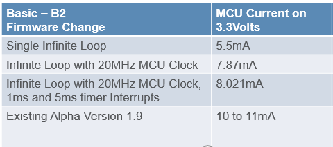
As per my product requirement i want to control the power consumption of micro controller.

Please suggest me to how to enable the low power modes(LPM0,1,2,3). Please check the code base and help me to get out off this issue.

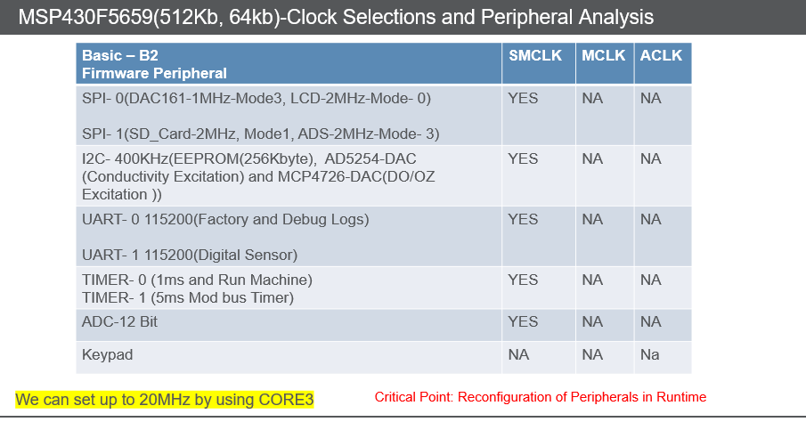
Please check attached file for reference..  All peripherals using SMCLK 

Low_power_mode.c
void configureHardware(void)
{
    //Initialize RTC
    RtcSettings();
    //Basic Clock Settings
    SYSINIT_Init_Micro();
    //DELAY 1ms TB0.0
    InitializeSystemTimer();
    // Initialize timer pool
    timer_pool_init();
    //5mSEC TRIGGER TA0.0
    Initialize5msTimer_start();
    //all modules gpio configurations
    AllModuleGpioConfig();
    //rs232 run machine
    initializeUSCI_B1_M_Lcd(void);
    //Internal ADC
    ADC_Initialize();
    I2CInitialization();
}

void RtcSettings(void)
{
    WDTCTL = WDTPW + WDTHOLD;                 // Stop WDT

    while(BAKCTL & LOCKBAK)                   // Unlock XT1 pins for operation
    BAKCTL &= ~(LOCKBAK);

    UCSCTL6 &= ~(XT1OFF);                     // XT1 On
    UCSCTL6 |= XCAP_3;                        // Internal load cap

    // Loop until XT1,XT2 & DCO stabilizes - In this case loop until XT1 and DCo settle
    do
    {
        UCSCTL7 &= ~(XT2OFFG + XT1LFOFFG + DCOFFG);
        // Clear XT2,XT1,DCO fault flags
        SFRIFG1 &= ~OFIFG;                      // Clear fault flags
    }while (SFRIFG1&OFIFG);                   // Test oscillator fault flag

    // Configure RTC_B
    //RTCCTL01 |= RTCRDYIE + RTCBCD + RTCHOLD;  // BCD mode, RTC hold, enable RTC read ready interrupt
    RTCCTL01 |= RTCRDYIE + RTCTEVIE + RTC_B_FORMAT_BINARY + RTCHOLD;  // BCD mode, RTC hold, enable RTC read ready interrupt

    // RTCYEAR = 0x2012;                         // Year = 0x2011
    // RTCMON = 0x06;                            // Month = 0x06 = June
    // RTCDAY = 0x22;                            // Day = 0x22 = 22nd
    // RTCDOW = 0x05;                            // Day of week = 0x05 = Friday
    // RTCHOUR = 0x11;                           // Hour = 0x11
    //RTCMIN = 0x59;                            // Minute = 0x59
    //RTCSEC = 0x45;                            // Seconds = 0x45

    RTCCTL01 &= ~(RTCHOLD);                    // Start RTC calendar mode

   // __bis_SR_register(GIE);       // Enter LPM3 mode with interrupts

    __bis_SR_register(LPM3_bits + GIE);       // Enter LPM3 mode with interrupts
    // enabled
    __no_operation();
}


void SYSINIT_Init_Micro(void)
{

    //Stop Watch Dog Timer............
    WDT_A_hold(WDT_A_BASE);
	
   /* PMM_setVCore(PMM_CORE_LEVEL_1); //DEFAULT 0

    DLY_US(1000);

    PMM_setVCore(PMM_CORE_LEVEL_2); //DEFAULT 0

        DLY_US(1000);*/

    PMM_setVCore(PMM_CORE_LEVEL_3); //DEFAULT 0

    DLY_US(1000);

    //Set DCO FLL reference = REFO

    UCS_initClockSignal( UCS_FLLREF,  UCS_REFOCLK_SELECT, UCS_CLOCK_DIVIDER_1 );

    //Set ACLK = REFO

    UCS_initClockSignal(UCS_ACLK, UCS_REFOCLK_SELECT, UCS_CLOCK_DIVIDER_1 );

    //Set Ratio and Desired MCLK Frequency  and initialize DCO

    UCS_initFLLSettle(UCS_MCLK_DESIRED_FREQUENCY_IN_KHZ, UCS_MCLK_FLLREF_RATIO );

    //Verify if the Clock settings are as expected

    clockValue = UCS_getSMCLK();

    clockValue = UCS_getMCLK();

    clockValue = UCS_getACLK();
}

void InitializeSystemTimer(void)
{

  	TB0EX0 = 6;

    // CCR0 interrupt enabled
  	TB0CCTL0 = CCIE;

  	TB0CCR0 = TIMER_B0_RELOAD;

	// SMCLK, continuous mode, clear TAR
  	TB0CTL = TBSSEL_2 | MC_2 | TBCLR;

    __bis_SR_register(GIE);       // Enter LPM0, enable interrupts

}

void Initialize5msTimer_start(void)
{
  //Start timer in continuous mode sourced by SMCLK
  Timer_A_initContinuousModeParam initContParam = {0};
  initContParam.clockSource = TIMER_A_CLOCKSOURCE_SMCLK;
  initContParam.clockSourceDivider = TIMER_A_CLOCKSOURCE_DIVIDER_7;
  initContParam.timerInterruptEnable_TAIE = TIMER_A_TAIE_INTERRUPT_DISABLE; // ENABLE
  initContParam.timerClear = TIMER_A_DO_CLEAR;
  initContParam.startTimer = false;
  Timer_A_initContinuousMode(TIMER_A0_BASE, &initContParam);

  //Initiaze compare mode
  Timer_A_clearCaptureCompareInterrupt(TIMER_A0_BASE,TIMER_A_CAPTURECOMPARE_REGISTER_0);

  Timer_A_initCompareModeParam initCompParam = {0};
  initCompParam.compareRegister = TIMER_A_CAPTURECOMPARE_REGISTER_0;
  initCompParam.compareInterruptEnable = TIMER_A_CAPTURECOMPARE_INTERRUPT_ENABLE;
  initCompParam.compareOutputMode = TIMER_A_OUTPUTMODE_OUTBITVALUE;
  initCompParam.compareValue = TIMER_A0_RELOAD;
  Timer_A_initCompareMode(TIMER_A0_BASE, &initCompParam);

  Timer_A_startCounter(TIMER_A0_BASE,TIMER_A_CONTINUOUS_MODE);

  __bis_SR_register(GIE);     // Enter LPM0 w/ interrupt
}


void initializeUSCI_B1_M_Lcd(void)
{
	
	#define CTRL_OPERATING_FREQ         20000000 // USER CONFIGURABLE

	#define SPI_CLK_186KHZ              186000
	#define SPI_CLK_1MHZ                1000000
	#define SPI_CLK_2MHZ                2000000
	#define SPI_CLK_4MHZ                4000000
	#define SPI_CLK_8MHZ                8000000
	#define SPI_CLK_20MHZ               20000000

    MLCD_CS_OUT_PIN_CONFIG(); //MLCD Chip select pin configured as a output

    MLCD_CS_HIGH();// CS HIGH

    MLCD_SPI_PERIPH_CONFIG(); //spi peripheral

    UCB0CTL0 = 0X09; //lsb first 8bit data ,mode 0, synchronous , master mode, 3pin spi
    UCB0CTL1 = 0X80; //fix smclk

	UCB0BR0 = (CTRL_OPERATING_FREQ/(SPI_CLK_2MHZ));    //2MHZ
	UCB0BR1 = 0;
    USCI_B_SPI_enable(USCI_B0_BASE);


     __bis_SR_register(GIE);

}


void ADC_Initialize(void)
{
	 ADC_12_BIT_PERIPH_PIN_CONFIG(); //P6SEL = 0x03;                              		// Set P6.3 as Peripheral Module - Enable A/D channel inputs
     P6SEL = 0x03;
	 ADC12CTL0 = ADC12ON + ADC12MSC + ADC12SHT0_2; 	// Turn on ADC12, set sampling time - 16 cycles
	 ADC12CTL1 = 0x021A;//ADC12SHP + ADC12CONSEQ_1;       		// Use sampling timer, single sequence, smclk
	 ADC12MCTL0 = ADC12INCH_3 + ADC12EOS;           // ref+=AVcc, channel = A0
 	 ADC12CTL0 |= ADC12ENC;                    		// Enable conversions

}


void I2CInitialization()
{
    UCB2CTL0 = 0X0F;
    UCB2CTL1 = 0XC0; //smclk
    UCB2BR0 = 50;									// Set I2C master speed  50 gives approx 400Khz clock at 20Mhz
    UCB2BR1 = 0;									// Set I2C master speed
}

  • Hi All,

    My application taking 107mW as of now using 20MHz clock. Is there any chance to get down the power consumption by using low power mode? 

    Please help me to get out of this issue. 

    Thanks,

    Krishna

  • I'm not familiar with the WEBENCH tools. Are you doing a simulation?

    If you're working with an actual MCU: User Guide (SLAU208Q) Sections 1.4-1.5 describe the low-power mode principles. There are also code examples (look for "lpm" in the name):

    http://dev.ti.com/tirex/explore/node?node=ABG2e0PYUJ7R3fBmUEL0mg__IOGqZri__LATEST

    That said, I don't know how to get an MSP430 to draw 33mA without some help from the external circuitry. What platform are you using? What other devices are connected?

  • Hey Krishna,

    As bruce mentioned, the power number for the MSP430 are listed in the datasheet.  Low power modes can bring your average power down, but it depends on the application on what percentage of the time you can stay in the modes and how fast you need to wake from sleep to perform your tasks.  

    Bruce also linked the code examples for you to see how to implement low power modes.

    Let us know what follow up questions you have.    

    Thanks,

    JD

  • Hi JD,

    Thank you for valuable support JD and Bruce,

    Sorry to delayed response, 

    I'm working on low power modes. As per bruce suggestions implemented LPM Modes. 

    Because of COVID-19 effect every one working from home. As of now don't have any setup with me to measure controller power consumption right now.

    Will share Results soon.

    As of now Controller consuming 40mW on 3.3Volts. Target is 20mw. 

    Stay at home Stay Safe

    Thanks,

    Krishna

  • 13mA is still very high for the MSP430 by itself [Ref Data Sheet (SLAS700D) Sec 5.4]. My guess is that you're seeing interaction with external devices, some combination of:

    1) Powering a (relatively) high-power external device from the power supply you're measuring.

    2) A bus conflict (driving opposite directions) with one or more of your pins.

    Improvement using LPM will be limited if these are happening. You can probably deduce much of this just with code+schematics.

  • Hi Bruce,

    Thank you for valuable support. 

    As of now we are using 20MHz Micro controller clock. Using SMCLK for all peripherals. Please refer (Peripheral Init) below module

    We are not entering into any application, simply we are using while loop with all peripherals(SPI- 2MHz, I2C - 400KHz, UART-115200), power consumption was 8 to 8.3 mA on 3.3Volts (27.39mW).  please refer Main.c file

    Is there any chance to decrease power consumption without LPM mode?

    Please check my initialization and let me know if anything want to change in initialization time. please refer Main.c file.  

    // refer attached Main.c file//

    void main()
    {
             configureHardware(); // Initialization of all peripherals as per application -

              while(1);  //consuming 8 to 8.3 on 3.3 //27.39mW

    }

    Application: - In application we should monitor monitor Data from External ADC and processing value should be show on LCD. Depends upon processing value we should be run 4-20mA by using one of the DAC, Also control some external modules with in 500ms cycle.

    1) Using two spi's each spi is connected to two external slaves those are running on different modes and frame packet format .

    while moving from one slave to another slave, we should be reconfigure spi in run time. Spi Speed 2MHz

    SPI 0- UCB0- LCD and DAC161

    SPI 1- UCB1- ADS1248 and SD-card

    2) I2C-  UCB2- 4 slaves(EEPROM, DAC4728, AD5254, MCP4726), speed 400KHz

    3) 1ms and 5ms timers 

    4) Internal ADC(12-Bit)

    5) UART- UCA1 - 115200 Baudrate

    Peripheral Init:


    Power Consumption:

    883728.Main.c
    void main()
    {
    	configureHardware();
    	while(1);	
    }
    
    void configureHardware(void)
    {
        //Initialize RTC
        RtcSettings();
        //Basic Clock Settings
        SYSINIT_Init_Micro();
        //DELAY 1ms TB0.0
        InitializeSystemTimer();
        // Initialize timer pool
        timer_pool_init();
        //5mSEC TRIGGER TA0.0
        Initialize5msTimer_start();
        //all modules gpio configurations
        AllModuleGpioConfig();
        //rs232 run machine
        initializeUSCI_B1_M_Lcd(void);
        //Internal ADC
        ADC_Initialize();
        I2CInitialization();
    	initializeUSCI_A1();
    }
    
    void RtcSettings(void)
    {
        WDTCTL = WDTPW + WDTHOLD;                 // Stop WDT
    
        while(BAKCTL & LOCKBAK)                   // Unlock XT1 pins for operation
        BAKCTL &= ~(LOCKBAK);
    
        UCSCTL6 &= ~(XT1OFF);                     // XT1 On
        UCSCTL6 |= XCAP_3;                        // Internal load cap
    
        // Loop until XT1,XT2 & DCO stabilizes - In this case loop until XT1 and DCo settle
        do
        {
            UCSCTL7 &= ~(XT2OFFG + XT1LFOFFG + DCOFFG);
            // Clear XT2,XT1,DCO fault flags
            SFRIFG1 &= ~OFIFG;                      // Clear fault flags
        }while (SFRIFG1&OFIFG);                   // Test oscillator fault flag
    
        // Configure RTC_B
        //RTCCTL01 |= RTCRDYIE + RTCBCD + RTCHOLD;  // BCD mode, RTC hold, enable RTC read ready interrupt
        RTCCTL01 |= RTCRDYIE + RTCTEVIE + RTC_B_FORMAT_BINARY + RTCHOLD;  // BCD mode, RTC hold, enable RTC read ready interrupt
    
        RTCCTL01 &= ~(RTCHOLD);                    // Start RTC calendar mode
    
        __bis_SR_register(LPM3_bits + GIE);       // Enter LPM3 mode with interrupts
        // enabled
        __no_operation();
    }


    void SYSINIT_Init_Micro(void)
    {
        //Stop Watch Dog Timer............
        WDT_A_hold(WDT_A_BASE);
    
        PMM_setVCore(PMM_CORE_LEVEL_3); //DEFAULT 0
    
        DLY_US(1000);
    
        //Set DCO FLL reference = REFO
    
        UCS_initClockSignal( UCS_FLLREF,  UCS_REFOCLK_SELECT, UCS_CLOCK_DIVIDER_1 );
    
        //Set ACLK = REFO
    
        UCS_initClockSignal(UCS_ACLK, UCS_REFOCLK_SELECT, UCS_CLOCK_DIVIDER_1 );
    
        //Set Ratio and Desired MCLK Frequency  and initialize DCO
    
        UCS_initFLLSettle(UCS_MCLK_DESIRED_FREQUENCY_IN_KHZ, UCS_MCLK_FLLREF_RATIO );
    
        //Verify if the Clock settings are as expected
    
        clockValue = UCS_getSMCLK();
    
        clockValue = UCS_getMCLK();
    
        clockValue = UCS_getACLK();
    }
    
    void InitializeSystemTimer(void)
    {
    
      	TB0EX0 = 6;
    
        // CCR0 interrupt enabled
      	TB0CCTL0 = CCIE;
    
      	TB0CCR0 = TIMER_B0_RELOAD;
    
    	// SMCLK, continuous mode, clear TAR
      	TB0CTL = TBSSEL_2 | MC_2 | TBCLR;
    
        __bis_SR_register(GIE);       // Enter LPM0, enable interrupts
    
    }
    
    void Initialize5msTimer_start(void)
    {
      //Start timer in continuous mode sourced by SMCLK
      Timer_A_initContinuousModeParam initContParam = {0};
      initContParam.clockSource = TIMER_A_CLOCKSOURCE_SMCLK;
      initContParam.clockSourceDivider = TIMER_A_CLOCKSOURCE_DIVIDER_7;
      initContParam.timerInterruptEnable_TAIE = TIMER_A_TAIE_INTERRUPT_DISABLE; // ENABLE
      initContParam.timerClear = TIMER_A_DO_CLEAR;
      initContParam.startTimer = false;
      Timer_A_initContinuousMode(TIMER_A0_BASE, &initContParam);
    
      //Initiaze compare mode
      Timer_A_clearCaptureCompareInterrupt(TIMER_A0_BASE,TIMER_A_CAPTURECOMPARE_REGISTER_0);
    
      Timer_A_initCompareModeParam initCompParam = {0};
      initCompParam.compareRegister = TIMER_A_CAPTURECOMPARE_REGISTER_0;
      initCompParam.compareInterruptEnable = TIMER_A_CAPTURECOMPARE_INTERRUPT_ENABLE;
      initCompParam.compareOutputMode = TIMER_A_OUTPUTMODE_OUTBITVALUE;
      initCompParam.compareValue = TIMER_A0_RELOAD;
      Timer_A_initCompareMode(TIMER_A0_BASE, &initCompParam);
    
      Timer_A_startCounter(TIMER_A0_BASE,TIMER_A_CONTINUOUS_MODE);
    
      __bis_SR_register(GIE);     // Enter LPM0 w/ interrupt
    }
    
    
    void initializeUSCI_B1_M_Lcd(void)
    {
    	
    	#define CTRL_OPERATING_FREQ         20000000 // USER CONFIGURABLE
    
    	#define SPI_CLK_186KHZ              186000
    	#define SPI_CLK_1MHZ                1000000
    	#define SPI_CLK_2MHZ                2000000
    	#define SPI_CLK_4MHZ                4000000
    	#define SPI_CLK_8MHZ                8000000
    	#define SPI_CLK_20MHZ               20000000
    
        MLCD_CS_OUT_PIN_CONFIG(); //MLCD Chip select pin configured as a output
    
        MLCD_CS_HIGH();// CS HIGH
    
        MLCD_SPI_PERIPH_CONFIG(); //spi peripheral
    
        UCB0CTL0 = 0X09; //lsb first 8bit data ,mode 0, synchronous , master mode, 3pin spi
        UCB0CTL1 = 0X80; //fix smclk
    
    	UCB0BR0 = (CTRL_OPERATING_FREQ/(SPI_CLK_2MHZ));    //2MHZ
    	UCB0BR1 = 0;
        USCI_B_SPI_enable(USCI_B0_BASE);
         __bis_SR_register(GIE);
    }
    
    void ADC_Initialize(void)
    {
    	 ADC_12_BIT_PERIPH_PIN_CONFIG(); //P6SEL = 0x03;                              		// Set P6.3 as Peripheral Module - Enable A/D channel inputs
         P6SEL = 0x03;
    	 ADC12CTL0 = ADC12ON + ADC12MSC + ADC12SHT0_2; 	// Turn on ADC12, set sampling time - 16 cycles
    	 ADC12CTL1 = 0x021A;//ADC12SHP + ADC12CONSEQ_1;       		// Use sampling timer, single sequence, smclk
    	 ADC12MCTL0 = ADC12INCH_3 + ADC12EOS;           // ref+=AVcc, channel = A0
     	 ADC12CTL0 |= ADC12ENC;                    		// Enable conversions
    
    }
    
    void I2CInitialization()
    {
        UCB2CTL0 = 0X0F;
        UCB2CTL1 = 0XC0; //smclk
        UCB2BR0 = 50;									// Set I2C master speed  50 gives approx 400Khz clock at 20Mhz
        UCB2BR1 = 0;									// Set I2C master speed
    }


    /******************************************************************************
                                UART- USCI_A1 P8.3,P8.2
    
    *******************************************************************************/
    void initializeUSCI_A1(uint32_t BaudRate)
    {
        //P8.2,3 = USCI_A2 TXD/RXD
        //GPIO_setAsPeripheralModuleFunctionInputPin(GPIO_PORT_P8, GPIO_PIN2 + GPIO_PIN3);
        DEBUG_CONIFG();
        //Baudrate = 9600, clock freq = 1.048MHz
        //UCBRx = 109, UCBRFx = 0, UCBRSx = 2, UCOS16 = 0
    
        USCI_A_UART_initParam param = {0};
    
        param.selectClockSource = USCI_A_UART_CLOCKSOURCE_SMCLK; //srk edit
    
        /*******************************************************************************
        BaudRate selection---
        param.clockPrescalar = 833; ----9600
        param.clockPrescalar = 416; ---19200;
        param.clockPrescalar = 69; ---115200;
    
        please change line number 100 inusci_a_uart.c file
        HWREG8(baseAddress + OFS_UCAxMCTL) = 0x06;
        HWREG8(baseAddress + OFS_UCAxMCTL) = 0x0A;
        HWREG8(baseAddress + OFS_UCAxMCTL) = 0x08;
        ****************************************************/
        param.clockPrescalar = ( CTRL_OPERATING_FREQ / BaudRate );//69; //115200
        param.firstModReg = 0;
        param.secondModReg = 2;
      
        param.parity = USCI_A_UART_NO_PARITY;
        param.msborLsbFirst = USCI_A_UART_LSB_FIRST;
        param.numberofStopBits = USCI_A_UART_ONE_STOP_BIT;
        param.uartMode = USCI_A_UART_MODE; //uart mode
    
        param.overSampling = USCI_A_UART_LOW_FREQUENCY_BAUDRATE_GENERATION;
    
        if (STATUS_FAIL == USCI_A_UART_init(USCI_A1_BASE, &param))
        {
            //return  STATUS_FAIL;//SRK-FIX
        }
    
        //Enable UART module for operation
        USCI_A_UART_enable(USCI_A1_BASE);
    
        //Enable Receive Interrupt
        USCI_A_UART_clearInterrupt(USCI_A1_BASE,USCI_A_UART_RECEIVE_INTERRUPT);
        USCI_A_UART_enableInterrupt(USCI_A1_BASE,USCI_A_UART_RECEIVE_INTERRUPT);
    
        __enable_interrupt();
    }

  • Hi Bruce,

    Thank you for valuable support. 

    As of now we are using 20MHz Micro controller clock. Using SMCLK for all peripherals. Please refer (Peripheral Init) below module

    We are not entering into any application, simply we are using while loop with all peripherals(SPI- 2MHz, I2C - 400KHz, UART-115200), power consumption was 8 to 8.3 mA on 3.3Volts (27.39mW).  please refer Main.c file

    Is there any chance to decrease power consumption without LPM mode?

    Please check my initialization and let me know if anything want to change in initialization time. please refer Main.c file.  

    // refer attached Main.c file//

    void main()
    {
             configureHardware(); // Initialization of all peripherals as per application -

              while(1);  //consuming 8 to 8.3 on 3.3 //27.39mW

    }

    Application: - In application we should monitor monitor Data from External ADC and processing value should be show on LCD. Depends upon processing value we should be run 4-20mA by using one of the DAC, Also control some external modules with in 500ms cycle.

    1) Using two spi's each spi is connected to two external slaves those are running on different modes and frame packet format .

    while moving from one slave to another slave, we should be reconfigure spi in run time. Spi Speed 2MHz

    SPI 0- UCB0- LCD and DAC161

    SPI 1- UCB1- ADS1248 and SD-card

    2) I2C-  UCB2- 4 slaves(EEPROM, DAC4728, AD5254, MCP4726), speed 400KHz

    3) 1ms and 5ms timers 

    4) Internal ADC(12-Bit)

    5) UART- UCA1 - 115200 Baudrate

    Peripheral Init:


    Power Consumption:

    6320.Main.c
    void main()
    {
    	configureHardware();
    	while(1);	
    }
    
    void configureHardware(void)
    {
        //Initialize RTC
        RtcSettings();
        //Basic Clock Settings
        SYSINIT_Init_Micro();
        //DELAY 1ms TB0.0
        InitializeSystemTimer();
        // Initialize timer pool
        timer_pool_init();
        //5mSEC TRIGGER TA0.0
        Initialize5msTimer_start();
        //all modules gpio configurations
        AllModuleGpioConfig();
        //rs232 run machine
        initializeUSCI_B1_M_Lcd(void);
        //Internal ADC
        ADC_Initialize();
        I2CInitialization();
    	initializeUSCI_A1();
    }
    
    void RtcSettings(void)
    {
        WDTCTL = WDTPW + WDTHOLD;                 // Stop WDT
    
        while(BAKCTL & LOCKBAK)                   // Unlock XT1 pins for operation
        BAKCTL &= ~(LOCKBAK);
    
        UCSCTL6 &= ~(XT1OFF);                     // XT1 On
        UCSCTL6 |= XCAP_3;                        // Internal load cap
    
        // Loop until XT1,XT2 & DCO stabilizes - In this case loop until XT1 and DCo settle
        do
        {
            UCSCTL7 &= ~(XT2OFFG + XT1LFOFFG + DCOFFG);
            // Clear XT2,XT1,DCO fault flags
            SFRIFG1 &= ~OFIFG;                      // Clear fault flags
        }while (SFRIFG1&OFIFG);                   // Test oscillator fault flag
    
        // Configure RTC_B
        //RTCCTL01 |= RTCRDYIE + RTCBCD + RTCHOLD;  // BCD mode, RTC hold, enable RTC read ready interrupt
        RTCCTL01 |= RTCRDYIE + RTCTEVIE + RTC_B_FORMAT_BINARY + RTCHOLD;  // BCD mode, RTC hold, enable RTC read ready interrupt
    
        RTCCTL01 &= ~(RTCHOLD);                    // Start RTC calendar mode
    
        __bis_SR_register(LPM3_bits + GIE);       // Enter LPM3 mode with interrupts
        // enabled
        __no_operation();
    }


    void SYSINIT_Init_Micro(void)
    {
        //Stop Watch Dog Timer............
        WDT_A_hold(WDT_A_BASE);
    
        PMM_setVCore(PMM_CORE_LEVEL_3); //DEFAULT 0
    
        DLY_US(1000);
    
        //Set DCO FLL reference = REFO
    
        UCS_initClockSignal( UCS_FLLREF,  UCS_REFOCLK_SELECT, UCS_CLOCK_DIVIDER_1 );
    
        //Set ACLK = REFO
    
        UCS_initClockSignal(UCS_ACLK, UCS_REFOCLK_SELECT, UCS_CLOCK_DIVIDER_1 );
    
        //Set Ratio and Desired MCLK Frequency  and initialize DCO
    
        UCS_initFLLSettle(UCS_MCLK_DESIRED_FREQUENCY_IN_KHZ, UCS_MCLK_FLLREF_RATIO );
    
        //Verify if the Clock settings are as expected
    
        clockValue = UCS_getSMCLK();
    
        clockValue = UCS_getMCLK();
    
        clockValue = UCS_getACLK();
    }
    
    void InitializeSystemTimer(void)
    {
    
      	TB0EX0 = 6;
    
        // CCR0 interrupt enabled
      	TB0CCTL0 = CCIE;
    
      	TB0CCR0 = TIMER_B0_RELOAD;
    
    	// SMCLK, continuous mode, clear TAR
      	TB0CTL = TBSSEL_2 | MC_2 | TBCLR;
    
        __bis_SR_register(GIE);       // Enter LPM0, enable interrupts
    
    }
    
    void Initialize5msTimer_start(void)
    {
      //Start timer in continuous mode sourced by SMCLK
      Timer_A_initContinuousModeParam initContParam = {0};
      initContParam.clockSource = TIMER_A_CLOCKSOURCE_SMCLK;
      initContParam.clockSourceDivider = TIMER_A_CLOCKSOURCE_DIVIDER_7;
      initContParam.timerInterruptEnable_TAIE = TIMER_A_TAIE_INTERRUPT_DISABLE; // ENABLE
      initContParam.timerClear = TIMER_A_DO_CLEAR;
      initContParam.startTimer = false;
      Timer_A_initContinuousMode(TIMER_A0_BASE, &initContParam);
    
      //Initiaze compare mode
      Timer_A_clearCaptureCompareInterrupt(TIMER_A0_BASE,TIMER_A_CAPTURECOMPARE_REGISTER_0);
    
      Timer_A_initCompareModeParam initCompParam = {0};
      initCompParam.compareRegister = TIMER_A_CAPTURECOMPARE_REGISTER_0;
      initCompParam.compareInterruptEnable = TIMER_A_CAPTURECOMPARE_INTERRUPT_ENABLE;
      initCompParam.compareOutputMode = TIMER_A_OUTPUTMODE_OUTBITVALUE;
      initCompParam.compareValue = TIMER_A0_RELOAD;
      Timer_A_initCompareMode(TIMER_A0_BASE, &initCompParam);
    
      Timer_A_startCounter(TIMER_A0_BASE,TIMER_A_CONTINUOUS_MODE);
    
      __bis_SR_register(GIE);     // Enter LPM0 w/ interrupt
    }
    
    
    void initializeUSCI_B1_M_Lcd(void)
    {
    	
    	#define CTRL_OPERATING_FREQ         20000000 // USER CONFIGURABLE
    
    	#define SPI_CLK_186KHZ              186000
    	#define SPI_CLK_1MHZ                1000000
    	#define SPI_CLK_2MHZ                2000000
    	#define SPI_CLK_4MHZ                4000000
    	#define SPI_CLK_8MHZ                8000000
    	#define SPI_CLK_20MHZ               20000000
    
        MLCD_CS_OUT_PIN_CONFIG(); //MLCD Chip select pin configured as a output
    
        MLCD_CS_HIGH();// CS HIGH
    
        MLCD_SPI_PERIPH_CONFIG(); //spi peripheral
    
        UCB0CTL0 = 0X09; //lsb first 8bit data ,mode 0, synchronous , master mode, 3pin spi
        UCB0CTL1 = 0X80; //fix smclk
    
    	UCB0BR0 = (CTRL_OPERATING_FREQ/(SPI_CLK_2MHZ));    //2MHZ
    	UCB0BR1 = 0;
        USCI_B_SPI_enable(USCI_B0_BASE);
         __bis_SR_register(GIE);
    }
    
    void ADC_Initialize(void)
    {
    	 ADC_12_BIT_PERIPH_PIN_CONFIG(); //P6SEL = 0x03;                              		// Set P6.3 as Peripheral Module - Enable A/D channel inputs
         P6SEL = 0x03;
    	 ADC12CTL0 = ADC12ON + ADC12MSC + ADC12SHT0_2; 	// Turn on ADC12, set sampling time - 16 cycles
    	 ADC12CTL1 = 0x021A;//ADC12SHP + ADC12CONSEQ_1;       		// Use sampling timer, single sequence, smclk
    	 ADC12MCTL0 = ADC12INCH_3 + ADC12EOS;           // ref+=AVcc, channel = A0
     	 ADC12CTL0 |= ADC12ENC;                    		// Enable conversions
    
    }
    
    void I2CInitialization()
    {
        UCB2CTL0 = 0X0F;
        UCB2CTL1 = 0XC0; //smclk
        UCB2BR0 = 50;									// Set I2C master speed  50 gives approx 400Khz clock at 20Mhz
        UCB2BR1 = 0;									// Set I2C master speed
    }


    /******************************************************************************
                                UART- USCI_A1 P8.3,P8.2
    
    *******************************************************************************/
    void initializeUSCI_A1(uint32_t BaudRate)
    {
        //P8.2,3 = USCI_A2 TXD/RXD
        //GPIO_setAsPeripheralModuleFunctionInputPin(GPIO_PORT_P8, GPIO_PIN2 + GPIO_PIN3);
        DEBUG_CONIFG();
        //Baudrate = 9600, clock freq = 1.048MHz
        //UCBRx = 109, UCBRFx = 0, UCBRSx = 2, UCOS16 = 0
    
        USCI_A_UART_initParam param = {0};
    
        param.selectClockSource = USCI_A_UART_CLOCKSOURCE_SMCLK; //srk edit
    
        /*******************************************************************************
        BaudRate selection---
        param.clockPrescalar = 833; ----9600
        param.clockPrescalar = 416; ---19200;
        param.clockPrescalar = 69; ---115200;
    
        please change line number 100 inusci_a_uart.c file
        HWREG8(baseAddress + OFS_UCAxMCTL) = 0x06;
        HWREG8(baseAddress + OFS_UCAxMCTL) = 0x0A;
        HWREG8(baseAddress + OFS_UCAxMCTL) = 0x08;
        ****************************************************/
        param.clockPrescalar = ( CTRL_OPERATING_FREQ / BaudRate );//69; //115200
        param.firstModReg = 0;
        param.secondModReg = 2;
      
        param.parity = USCI_A_UART_NO_PARITY;
        param.msborLsbFirst = USCI_A_UART_LSB_FIRST;
        param.numberofStopBits = USCI_A_UART_ONE_STOP_BIT;
        param.uartMode = USCI_A_UART_MODE; //uart mode
    
        param.overSampling = USCI_A_UART_LOW_FREQUENCY_BAUDRATE_GENERATION;
    
        if (STATUS_FAIL == USCI_A_UART_init(USCI_A1_BASE, &param))
        {
            //return  STATUS_FAIL;//SRK-FIX
        }
    
        //Enable UART module for operation
        USCI_A_UART_enable(USCI_A1_BASE);
    
        //Enable Receive Interrupt
        USCI_A_UART_clearInterrupt(USCI_A1_BASE,USCI_A_UART_RECEIVE_INTERRUPT);
        USCI_A_UART_enableInterrupt(USCI_A1_BASE,USCI_A_UART_RECEIVE_INTERRUPT);
    
        __enable_interrupt();
    }

  • 8mA is a reasonable measurement for a program spinning (active mode) at 20MHz. It sounds like you've been able to arrange to measure only the MCU.

    As a very simple experiment, replace your while(1) loop with "while (1) {LPM0;}" and measure again. You should see the current drop; I don't see this particular number (current at LPM0 at 20MHz) in the Data Sheet, but I'm guessing 2-3mA. 

    There are non-LPM things you can do to reduce current, but the effects are relatively small compared to what LPM gives you. Configuring unused pins, e.g., will probably give you 0.3mA. These are things you should do for their own sake, but maybe not yet.

  • Hi Bruce,

    We measure across MCU on 3.3Volts. 

    Experiments:-

    1) //single while loop - - power consumption is 5.5mA on 3.3V = 18.15mW

           void main()

           { while(1);}

    2) //single while loop with LPM0 - power consumption is 1.3mA on 3.3V = 4.2mW

            void main()

            {

    while(1)

    {

    __bis_SR_register(LPM0_bits); // Enter LPM0//do nothing /

    }

    But my application have to monitor the data continuously from sensor and have to display on UI and also control high accuracy devices in industries. 

    For example if i use LPM0, Controller should be in sleep mode xms(milli seconds) and woke up by Interrupts to do rest of the application,  am i right? Please correct me if anything wrong. 

    At present i'm using LPM0 mode in my application for testing how much current will reduce compared to active mode. And also woke up every 20ms. to run application. In this scenario i'm facing performance issue(i.e time lag  observed,)

    In active mode it will take 500ms to update the new value on UI, after implementing the LPM0 it will take more than 2 seconds. 

    Is there any chance to reduce power consumption of MCU on 3.3Volts without low power mode. 

     Main concern is have to monitor and control the external sensitive devices continuously. 

    Please guide me and suggest  me

    Implementation:-

    1) First step of micro controller configured as an output pins of all GPIO's, and after that main initialization started. 

    2) Disabling the peripherals after one time use.

    3) Run time Enable and Disable of peripherals. 

    Note:- Present we are in Lock down period in INDIA, We don't have proper hardware setup to test as of now. Will share accurate results after APRIL-14th. 

    Thanks,

    Krishna

  • The point of that experiment was to provide a baseline for what you can achieve with LPM(0). This is a useful number to have in mind.

    If you don't want to use LPM, you should at least go through the guidelines in User Guide (SLAU208Q) Sec 1.4-6. Properly configuring unused pins (Sec 1.6) can make a visible difference. Some of the other methods, e.g. slowing down the clock and lowering Vcc, may not apply to your application.

    The point of LPM is to find idle time -- when your program has nothing to do -- and idle the CPU (and maybe other things) during that time. It may be that your application (vs your program) has no idle time -- such applications exist, but they're rare. More likely, your application has idle time, but it's hidden in your program.

    You mentioned that you have to service your devices "continuously", which isn't quite correct. Since your program is doing other things, it can't be servicing the devices (truly) continuously. I'm not "playing with words" here -- the point is that each device has a minimum service period (>0), during which its state won't change; servicing it more often than that (e.g. spin loop) is a waste, and the CPU might as well idle. This minimum service period(s) is probably described in your design/specification document and/or an external device's datasheet.

    As a simple example, for an I2C at 400kHz, once you give it a Tx byte you won't hear from it for (20*2.5*9bits)=450 clocks, so there's no point in looking until then. Similarly, when you start the DMA to your SD card, it will be running for at least 8bits*(BRW=1)*512bytes=4096 clocks before the CPU needs to check it. From now until then is your idle time.

**Attention** This is a public forum