This thread has been locked.

If you have a related question, please click the "Ask a related question" button in the top right corner. The newly created question will be automatically linked to this question.

MSP430FR2476: Help with temp sensor calc

Part Number: MSP430FR2476

Hello,

I have my adc reading the temp sensor module in my MSP430FR device, but I'm a little lost as to how to interpret the results.  Using the equation below

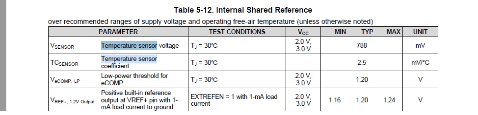
Is V_30 degrees C the below value V_sensor in the below table (top row)?  

If so - is the proper way to calculate temp the following?

Read ADC value (my value is 0xF0) and convert that to a voltage.  In my case using a 3.3V reference I get (3.3 / (2^10)) * 240.  0xF0 = 240 so I just use the decimal value and this yields about 773mV.  I then plug this in to the equation in the first screenshot?

It seems like multiplying the voltage difference by such a small number as 0.00355 will not yield very accurate results.  Is there anyone who could elaborate on this process from the point of having an adc code from the temp sensor?

Thanks.

  • Hi Bruce,

    Thank you for responding that is a great reference!  I see a lot of other terms there that aren't in the datasheet equation.  Is this a derivative of that equation and do you have any info on how the equation in code you link me to came about?  

    For example,

    IntDegC = (temp-CALADC_15V_30C)*(85-30)/(CALADC_15V_85C-CALADC_15V_30C)+30;

    where does the 85 come from in the (85-30) term?  

  • Also,

    I found my coefficient values that are used in the example code, but mine go from 30C to 105C rather than 85C.  I am assuming I can just use this wider range and replace the 85 in the example with 105.  Is that correct?

  • Hm. That does seem like an oversight in the Example. [I'm supposing you found Data Sheet (SLASEO7B) Table 6-30.]

    Yes, substituting 105 for 85 would be my first guess as to what to do. I haven't had occasion to use the temp sensor on the FR2476.

  • This may be a dumb question, but there are cal coefficients for 1.5V, 2.0V and 2.5V - I'm assuming the adc needs to use one of those voltages as it's ref voltage in order to use these coefficients?

  • I'm surprised how confusing TI's internal temp sensors are to actually implement.  

    I not have this up and running with the internal 2.5V reference and the 10bit adc.  With my configuration at room temperature I'm getting 0x144 out of the temp sensor at room temp in my apt and this is pretty close to the 788mV shown in the datasheet for my specific chip.  I'm referring to table 5-12 above from my MSP430FR2476 data sheet.  My raw adc reading converts pretty closely to what they get at 30 degrees C.  I can't figure out how to use equation 11 in section 2.2.9 of the MSP430FR2xx family datasheet.  

  • I suppose that, since the calibration constants are denominated in ADC ticks, you should use 12-bit mode (as in the Example).

    That said, on my FR2476 Launchpad, I also get around 30C from the Example code. If I move the code to an FR2355, I get 23C, which is more or less correct and matches what the FR2355 ADC12_16 example says.

    I now wonder whether my (and maybe your) calibration constants aren't correct. Maybe something about "XFR" (vs "MSP430FR") devices?

  • Were you using the following equation?

    IntDegC = (temp-CALADC_15V_30C)*(85-30)/(CALADC_15V_85C-CALADC_15V_30C)+30;

    Whats really odd to me is that the datasheet says 30C is 788mV and if I run my adc and read the temp sensor and take the adc code and convert it to voltage by way of (2.5V/1024)*ADC_CODE I get ~770mV or ~30C.  This is with no equation just converting the adc code to voltage.

  • The ADC12_16 examples for the FR2476 and FR2355 are slightly different, but both use that formula. 

    I'm not an expert on the temperature sensor. I figured that part of the Calibration had to do with the package thermal conductivity, i.e. accounting for the difference ("large offset") between case/ambient temperature and junction temperature (Tj). But my FR2476 chip doesn't seem to do that (my FR2355 chip does), so I wonder if my "ancient" (June 2019 I think)  pre-production device just doesn't have the right Calibration constants. (I wouldn't know by looking.)

  • Hey Bruce, I think I have this working now.  I think my issues boiled down to running the adc in 10bit mode and using the wrong math.  I wish TI would comment on that equation from the datasheet.  I don't see how equation can be used.  Anyways, thanks for the help in finding a useful equation - I would have never found that.

  • Hello,

    Thanks for your findings. Yes, there are some misunderstandings in the datasheet.

    I think there will be some comments on how to use the calibration data in next update.

**Attention** This is a public forum