


Hi, I would like to connect MSP430F5438A with the MPRLS pressure sensor via I2C.
The crystal I used is 29.5 MHz, and I use UCB1CLK and UCB1SDA.
I tried the I2C example code "msp430x54xA_uscib0_i2c_06.c" to ensure that MSP430 can send the data out.
However, I found that the code always stop in the interrupt vector.
Especially it will stop in
Here is my code:
#include <msp430.h>
#define CRYSTAL_295
unsigned char TXData;
unsigned char TXByteCtr;

void init_clock(void);

int main(void)
{
  int i;
  //WDTCTL = WDTPW + WDTHOLD;                 // Stop WDT
  init_clock();
  P3SEL |= BIT7;                            // Assign I2C pins to USCI_B0
  P5SEL |= BIT4;
  __disable_interrupt();
  UCB1CTL1 |= UCSWRST;                      // Enable SW reset
  UCB1CTL0 = UCMST + UCMODE_3 + UCSYNC;     // I2C Master, synchronous mode
  UCB1CTL1 = UCSSEL__SMCLK + UCSWRST;            // Use SMCLK, keep SW reset
  UCB1BR0 = 12;                             // fSCL = SMCLK/12 = ~100kHz
  UCB1BR1 = 0;
  UCB1I2CSA = 0x18;                         // Slave Address is 048h
  UCB1CTL1 &= ~UCSWRST;                     // Clear SW reset, resume operation
  for(i=0;i<100;i++) {};
  UCB1IE |= UCTXIE;                         // Enable TX interrupt

  TXData = 0x01;                            // Holds TX data

  while (1)
  {
    TXByteCtr = 1;                          // Load TX byte counter

    while (UCB1CTL1 & UCTXSTP);             // Ensure stop condition got sent
    UCB1CTL1 |= UCTR + UCTXSTT;             // I2C TX, start condition

    __bis_SR_register(LPM0_bits + GIE);     // Enter LPM0 w/ interrupts
    __no_operation();                       // Remain in LPM0 until all data
                                            // is TX'd

    TXData++;                               // Increment data byte
  }
}

//------------------------------------------------------------------------------
// The USCIAB0_ISR is structured such that it can be used to transmit any
// number of bytes by pre-loading TXByteCtr with the byte count.
//------------------------------------------------------------------------------

#pragma vector = USCI_B1_VECTOR
__interrupt void USCI_B1_ISR(void)

{
  switch(__even_in_range(UCB1IV,12))
  {
  case  0: break;                           // Vector  0: No interrupts
  case  2: break;                           // Vector  2: ALIFG
  case  4: break;                           // Vector  4: NACKIFG
  case  6: break;                           // Vector  6: STTIFG
  case  8: break;                           // Vector  8: STPIFG
  case 10: break;                           // Vector 10: RXIFG
  case 12:                                  // Vector 12: TXIFG
    if (TXByteCtr)                          // Check TX byte counter
    {
      UCB1TXBUF = TXData;                   // Load TX buffer
      TXByteCtr--;                          // Decrement TX byte counter
    }
    else
    {
      UCB1CTL1 |= UCTXSTP;                  // I2C stop condition
      UCB1IFG &= ~UCTXIFG;                  // Clear USCI_B0 TX int flag
      __bic_SR_register_on_exit(LPM0_bits); // Exit LPM0
    }
    break;
  default: break;
  }
}

/*********************************************************************
Function : init_clock
Purpose : Initial system clock
Parameter : none
Return value : none
*********************************************************************/
void init_clock(void)
{
	unsigned int i;
	WDTCTL = WDTPW + WDTHOLD; // Stop watchdog timer
	P5SEL |= 0x0C; // Port select XT2
	UCSCTL6 &= ~XT2OFF; // Enablee XT2 even if not used
#ifdef CRYSTAL_295
	UCSCTL6 |= 0xC000; // Enablee XT2 even if not used
#endif
	UCSCTL3 |= SELREF_2; // FLLref = REFO
	UCSCTL4 |= SELA__XT2CLK;//Select source fromXT2-16M
	UCSCTL4 |= SELS_5 + SELM_5; // SMCLK=MCLK=XT2-16M
	_NOP();
#ifdef CRYSTAL_295
	UCSCTL5 |= DIVM__2 + DIVS__32+ DIVA__2;  // Crystal -> 29.5MHz
#endif
	do
	{
		UCSCTL7 &= ~(XT2OFFG + XT1LFOFFG + DCOFFG);// Clear XT2,XT1,DCO fault flags
		SFRIFG1 &= ~OFIFG; // Clear fault flags
		for(i=0;i<0xFFFF;i++); // Delay for Osc to stabilize
	}while (SFRIFG1&OFIFG); // Test oscillator fault flag
 }
I use IAR Embedded Workbench IDE and set the breakpoint to check the problem.
I am sure it will go into the interrupt vector as follows:
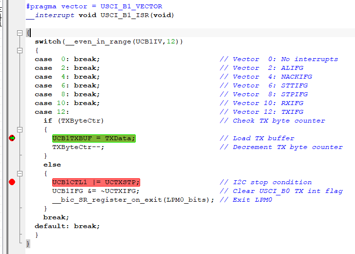
However, if I click "go" to continue the program, it won't go into the next breakpoint: UCB1CTL1 |= UCTXSTP
I have no idea what's going on...Is there anyone can help me with this issue?
Thank you very much in advance!
Michelle

