This thread has been locked.

If you have a related question, please click the "Ask a related question" button in the top right corner. The newly created question will be automatically linked to this question.

MSP430FR5969: SPI DMA full duplex master/slave

Part Number: MSP430FR5969

I have been using the DMA for full duplex SPI transfers between a pair of MSP430FR5969 LaunchPad kits master/slave operating at 16MHz (MCLK & SMCLK).  Eventually I will be using an I need full duplex SPI communications between a non-MSP master and an MSP430FR5969 slave.  The MSP430s work fine up to somewhere between a bit-rate of 2.67MHz and 3.2MHz and then things start to break down.  I noticed that the master was sending extra bytes as I sped up the clock.  I couldn't find anything definitive on maximum SPI speed, but I assume that it should work up to 8MHz (some other controllers that I have used with DMA have no issue at half the system clock rate). I have verified the extra bytes with a protocol analyzer.

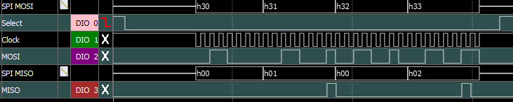
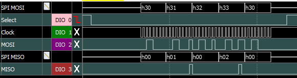
At any rate I now have just the master connected to the protocol analyzer.  I am using a buffer of 4 bytes for my test.  With the clocks at 16MHz and using a divisor of 8, 7 & 6 the MSP430 sends 4 bytes.  With a bit-rate divisor of 5, 4  & 3 the MSP430 send 5 bytes and when the divisor is 2 it sends 7 bytes.  The master is in 3-wire mode, I do hold the DMA in reset when I change the bit-rate divisor.

The thing that is really hard for me to understand is why the MSP430 sends more bytes than it should.

I can understand a speed limit (still not sure what it should be), I need an 8MHz full duplex link, from what I can tell the DMA takes 2 clocks to store the data (there are 8 per byte) and there is a transmit/receive buffer.

I have tried a couple of ways of starting the transfer (initial write to SPI Tx and toggling the Tx IFG) both work correctly as long as you make the size adjustment when writing to Tx register.

I can change the bit-rate between messages on the fly and and my full duplex setup continues to work fine at divisors of 6-8.  Runs forever, I also implemented a checksum on one implementation just to make sure not else strange was going on.

I have about the smallest set of code/project that I could share.  If anyone has a suggestion, I would be happy to try it.  Hopefully it is just something simple.

Regards

  • DMA requires more than 2 cycles. See 11.2.7 for the details. Minimum of 4 cycles and could be more depending on low power mode.(Keeping in mind also that the FRAM wait states will almost certainly add to the time to access data if it is in FRAM.)

    Maximum input clock speed for the USCI is 16MHz so 8Mbps shouldn't be a problem although that leaves you only 16 MCLKs per byte. Which makes getting data in and out fast enough very tricky.

  • If you have a test case (particularly a small one) I encourage you to post it. There's lots of eyes here, and someone might see something.

    Are you by chance using DMALEVEL=1? I do it (but I feel guilty about it!) but I always wondered whether there could be a race with TXIFG at very high speeds. 

  • I did take a look at 11.2.7, but it didn't seem like a show stopper at these speeds (4 or 8 MHz for example).

    The buffer is in RAM (if I am reading the linker & debug information correctly) and I am not in a low-power mode.

    The transactions occur periodically on the order of 10s of milliseconds in a 32 byte frame (4 for my testing). The SPI bus is running at 8MHz and there are several other devices on the bus.

    Thanks

  • What would be the preferred method of posting?  I could export from CCS in one of the options.

    I am using DMALEVEL one, TxIFG as trigger.  The actual message is a 32 byte frame that is transmitted every few tens of milliseconds on a SPI bus operating a 8MHz with several other devices.

    I am using a 4 byte message in my test code because it is easier to see on the protocol analyzer and I only transmit every few seconds.

    As far a a race condition... it seems plausible.  I have noticed that the extra bytes are a duplicate of the beginning of the message (appears to wrap).  This would suggest that the source address is getting reinitialized, but the terminal count is not being recognized until much later.  This may suggest a not very pretty work around.

    I am operating in repeated single mode.  I have also experimented with a couple of different ways to start the transfer.

    Also, when both master and slave are connected the slave also "sees" the extra bytes.

    Thanks

  • If your code is just one .c file, you can just attach it. (I personally am stuck at CCS v8, so I can't import v9/v10 projects.)

    The DMALEVEL thing is just a suspicion, I have no evidence. I've always been bothered by that sentence in paragraph 1 of User Guide Sec 11.2.3.2 (it appears in pretty much every User Guide) "For proper operation, level-sensitive triggers can only be used when external trigger DMAE0 is selected as the trigger", with no further explanation. I can imagine some hazards, but it certainly seems to operate properly in some/most cases. (That's why I joked about "feeling guilty" above.)

    DMALEVEL=1 is very convenient to get around the TXIFG-edge requirement, but it isn't really necessary. The alternative is to start the DMA at the second byte, and explicitly write the first byte to TXBUF to get that initial rising edge. 

  • You don't need to post all of your code or even a lot. Just the setup for the DMA and where you start sending. As an example, this is how I do it, although at a much lower bit rate and in UART mode:

         /*
           One time DMAC setup.
    
           Triggered by UCA0 transmit register empty IFG.
           Single transfer per trigger, source increments, byte at a time.
           Destination is the UCA0 transmit register.
    
           Note that the TI GCC compiler generates some really awful code to
           set the source and destination addresses. I added 16 bit register
           definitions to the device header file.
         */
         DMACTL0 = DMA0TSEL__UCA0TXIFG;
         DMA0CTL = DMADT_0|DMASRCINCR_3|DMADSTBYTE|DMASRCBYTE;
         DMA0DAL = (int)&UCA0TXBUF;
    

      /*
        Use DMA0 to transfer the packet to the transmit register. Most of the 
        setup was performed during initialization. The first two bytes are
        transferred directly to the UART. The DMAC will handle the rest.
       */
      DMA0SAL = (int)bufp;
      DMA0SZ = i;                 // count of bytes to transfer
    
      UCA0TXBUF = 0xff;
      // the transmit hold register should clear almost instantly
      while(!(UCA0IFG&UCTXIFG))  
        ;
    
      DMA0CTL |= DMAEN;           // enable DMAC
      UCA0TXBUF = SYNC;           // transmit first byte of packet


  • My bad, DMALEVEL is zero, sorry for the confusion.  I mentioned in the opening that I was using the TxIFG and then said DMALEVEL one which was incorrect.

    I have tried both writing the first byte to the transmitter and toggling the flag, both work fine with the appropriate count.

    Here is the setup:

    DMA_DMACTL0
    0013
    DMA_DMACTL1
    0000
    DMA_DMACTL2
    0000
    DMA_DMACTL3
    0000
    DMA_DMACTL4
    0000    0000    0000
    DMA_DMAIV
    0000
    DMA_DMA0CTL
    43C0
    DMA_DMA0SA
    1CA8    0000
    DMA_DMA0DA
    064E    0000
    DMA_DMA0SZ
    0004    0000    0000

    I'm going to look into posting code or upload the 3 files that make up the test code.  Kind of busy this morning, will try and get to it soon.

    Thanks

  • Setups and protocol screen shots.

    So, here is the setup...

     #define SRC_TRIGGER DMA_TRIGGERSOURCE_19    // Transmit interrupt flag

      static DMA_initParam DMAsourceMSaddr=    // Outgoing bytes
            {    // Transmit buffer to slave
            .channelSelect=DMA_CHANNEL_0,    // Slave channel
            .transferModeSelect=DMA_TRANSFER_REPEATED_SINGLE,    // CPU OPs SLAU37O 11.2.2.3
            .triggerSourceSelect=SRC_TRIGGER,    // SLAS704G 6.10.8 (opt 19, transmit)
            .transferSize=sizeof(DMAmessageType)-(KICK_START?Zero:One),    // Depends on how started
            .transferUnitSelect=DMA_SIZE_SRCBYTE_DSTBYTE,    // BYTE sized
            .triggerTypeSelect=DMA_TRIGGER_RISINGEDGE    //SLAU367O 11.2.3.1/2
            };

        HWREG16(EUSCI_B0_BASE+OFS_UCBxCTLW0)=MS_SPI_MASTER_RUN|One;
        HWREG16(EUSCI_B0_BASE+OFS_UCBxBRW)=BAUDRATE_DIV_DMA;    // Slow rate to start
        HWREG16(EUSCI_B0_BASE+OFS_UCBxCTLW0)=MS_SPI_MASTER_RUN;

        DMA_setDstAddress(    // Commands to slave via SPI port
            DMA_CHANNEL_0,// Data channel out
            EUSCI_B_SPI_getTransmitBufferAddress(EUSCI_B0_BASE),// Destination is SPI B TX Register
            DMA_DIRECTION_UNCHANGED);    // Fixed location

        DMA_setSrcAddress(    // Command buffer to slave
            DMA_CHANNEL_0,// Data channel out
            (uint32_t)( &(DMAmsg.bytes[Zero])+(KICK_START?Zero:One)),    // Kick ^ pre-load first byte
            DMA_DIRECTION_INCREMENT);    // Increment the address


    Below are examples of  three 4 byte DMA transfers (slow, medium & fast clocks), the only thing that is changed is the SPI clock rates.

  • I don't know where the screen shots went, I had used the snipping tool to paste them into the message.  It was there before I hit the reply button.

  • PNG SPI waveform captures.

  • I think that you have used the wrong transfer mode. I used single where you are using repeated single. With single the transfer ends when the count goes to zero while with repeated single, it does not. Since the SPI port will keep sending data and generating edges on TXIFG, you have to do something to stop it.

    Missing from your code is how you start the transfer and it looks how it ends is also important. At the higher bit rates the DMA could process several more bytes after it throws a transfer complete interrupt and before you can turn off the bubble machine.

  • Unsolicited: If (as your description suggests) you're using the DMA in both directions (Rx/Tx) be sure to give the Rx side higher priority, to avoid overruns. It's possible that the thing David pointed out has been hiding this symptom.

  • I will give the single transfer mode a try.  Today is a short day for me and it will probably be next week before I can get to it.  However, the way I read the documentation on repeated single and the way it appears to operate is that it decrements the count. Otherwise it would not work at lower speeds.  I think the protocol analyzer shows that.  As I mentioned at speeds up to somewhere just below 3MHz it works fine.

    As far as starting the transfer, I modify the count to (length-One, see the little KICKSTART piece above) for the transfer when writing the first byte to the SPI and leave it at full count when toggling the TxIFG.  Both of these start-up methods work, and both have exactly the same result.

    #if !KICK_START
            EUSCI_B_SPI_transmitData(EUSCI_B0_BASE, TestBuffer[Zero].bytes[Zero]);    // Send first byte
    #endif
    #if KICK_START
            UCB0IFG&= ~UCTXIFG;    // Kick start (opt)
            UCB0IFG|=UCTXIFG;    // Kick start (opt)
    #endif

    I use the DMA complete interrupt to de-assert the chip select (CS).  There is a little issue with this, at low speeds the DMA transfer is complete before the last couple of bits are shifted out.  So, for testing I just sit and spin in the interrupt and look at the busy flag for the SPI.  The better solution would have been to send one more (dummy) byte and have the DMA complete interrupt clear the CS.

                DMA0CTL&=~DMAEN;
                DMA_clearInterrupt(DMA_CHANNEL_0);
                DMAzeroCount++; // number of transfers
                while ( UCB0STATW&UCBUSY )    // Must wait here or truncates last byte (for testing)
                {
                    ; // Could also send an extra byte, might be cleaner
                }

    For my test case this works fine.  Now to recap:

    • When I use two evaluation boards and set up as master/slave at up to 2.67MHz+
      • I get flawless full duplex communication between the 2 boards
      • They run for days without error, the payload is a 32 byte frames with a checksums
      • The boards are setup as described above.
    • I have a LabView program that also acts as master
      • I got some funny slave behavior with it (still need to look at that), which is why I went with a MSP430 master
      • Got the same results on slave couldn't keep up (but I now have information)

    I can still send all the test code if anyone wants a deeper dive.

    Thanks

  • Good point that does make sense and that is an easy change.

    Thanks

  • [Putting words in David's mouth:] At lower speeds your DMA interrupt has enough time to get in and stop the DMA before it sends out more bytes, but at higher speeds it doesn't. I also vote for DMADT=0 (DMA_TRANSFER_SINGLE).

    Try using the Rx side for your DMA completion interrupt. By then you know the SPI is finished.

    [Edit: I personally find the name "single transfer" for DMADT=0 to be non-intuitive. It's actually "single transfers up to DMASZ, then stop". I always refer to the flow charts, in this case UG (SLAU367P) Fig 11-3, where you can see the two paths for DMADT=0 vs 4.]

  • The DMA_TRANSFER_SINGLE did solve the extra bytes of transmission. Non-intuitive is a good description, in going over the documentation and flow charts again I see where the extra bytes come from.

    Now since I have a SPI master that I can send a reliable number of bytes as a simulation to the real system.  I can work on the SPI slave which is the real target of the work. 

    Regards & thanks.

**Attention** This is a public forum