This thread has been locked.

If you have a related question, please click the "Ask a related question" button in the top right corner. The newly created question will be automatically linked to this question.

CCS/MSP430G2231: P1.3 button not working

Part Number: MSP430G2231

Tool/software: Code Composer Studio

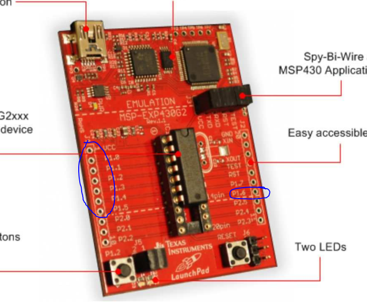
Hello everyone, I have a question about the msp430 board. I am doing a frequency meter(which is working), but I want to switch the input on the LCD with the button P1.3 but there is one problem I try to activate the P1.3 pull-up resistor cuz without it the LCD just switches back and forward between two states in a switch statement.

static unsigned clock_input = 0;         //TBC
void set_input(void)
{
    lcd_init();
   // const unsigned char z = 0;        
    switch(clock_input) {
        default:
        clock_input = 0;
        case 0:
           TACTL = TASSEL_2;

           break;          
       case 1:
            TACTL = TASSEL_1;

           break;
    }
}

this is the switch statement

if(!(P1IN&BIT3)) {
clock_input++;
set_input();
}

and this is how I want to switch between TASSEL_1 and TASSEL_2.

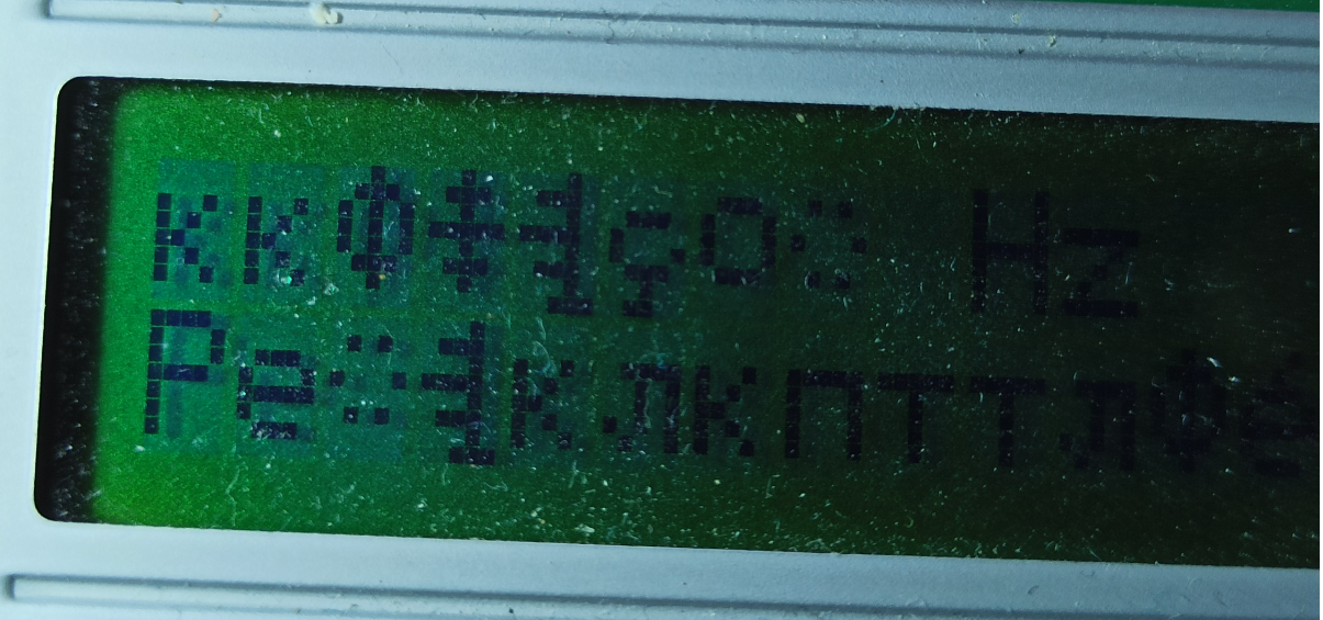
ill show you pictures

sorry for the quality on this one but here the LCD is showing the internal frequency no problem, but it's constantly switching between 32kHz and the 1MHz frequency from TASSEL_2(1MHz).

I think the problem is that the pull up is not defined and its switching between the two statements.

but when I insert the code for the pull-up 

P1OUT |= BIT3;
P1REN |= BIT3;

The code loses its mind and random symbols start to appear just by adding the P1REN line. I am trying to figure this out for hours and I really have no idea whats the problem.

  • Starting with the obvious: Do you have anything else connected to P1.3?

    Are you using one of the Launchpads? The G2ET, and some revisions of the (older) G2 Launchpad have an  external pullup on P1.3 (47K on the G2ET).

    When -- in particular how frequently -- are you checking P1IN?

    Since you're talking about a physical button, beware of switch bounce.

    A little more context -- more code, and maybe a schematic -- could provide better guesses.

  • Well, I had an LCD pin connected to P1.3 but I moved it to 1.7 and still the same problem. About the schematic, it's just the MSP-exp430g2 board

    #define DR P1OUT = P1OUT | BIT4          // define RS high
    #define CWR P1OUT = P1OUT & (~BIT4)      // define RS low
    #define READ P1OUT = P1OUT | BIT5        // define Read signal R/W = 1 for reading
    #define WRITE P1OUT = P1OUT & (~BIT5)    // define Write signal R/W = 0 for writing
    #define ENABLE_HIGH P1OUT = P1OUT | BIT6 // define Enable high signal
    #define ENABLE_LOW P1OUT = P1OUT & (~BIT6) // define Enable Low signal
    
    void data_write(void)
    {
    ENABLE_HIGH;
    delay(2);
    ENABLE_LOW;
    }
    
    void data_read(void)
    {
    ENABLE_LOW;
    delay(2);
    ENABLE_HIGH;
    }
    
    void check_busy(void)
    {
    P1DIR &= ~(BIT3); // make P1.3 as input
    
    while((P1IN&BIT3)==1)
    {
    data_read();
    }
    P1DIR |= BIT3; // make P1.3 as output
    }
    
    void send_command(unsigned char cmd)
    {
    check_busy();
    WRITE;
    CWR;
    P1OUT = (P1OUT & 0xF0)|((cmd>>4) & 0x0F); // send higher nibble
    data_write(); // give enable trigger
    P1OUT = (P1OUT & 0xF0)|(cmd & 0x0F); // send lower nibble
    data_write(); // give enable trigger
    }
    
    void send_data(unsigned char data)
    {
    check_busy();
    WRITE;
    DR;
    P1OUT = (P1OUT & 0xF0)|((data>>4) & 0x0F); // send higher nibble
    data_write(); // give enable trigger
    P1OUT = (P1OUT & 0xF0)|(data & 0x0F); // send lower nibble
    data_write(); // give enable trigger
    }
    
    void send_string(char *s)
    {
    while(*s)
    {
    send_data(*s);
    s++;
    }
    }
    
    void lcd_init(void)
    {
    P1DIR |= 0xFF;
    P1OUT &= 0x00;
    send_command(0x33);
    send_command(0x32);
    send_command(0x28); // 4 bit mode
    send_command(0x0E); // 
    send_command(0x01); // cursor position
    send_command(0x06); // increment cursor
    send_command(0x80); // 1 row 1st column
    }

    And this is how I send data to the LCD.

  • > while((P1IN&BIT3)==1)

    This condition is always false, since BIT3==8. Try something like:

    > while((P1IN&BIT3)==BIT3)

    On the face of it, this just bypasses your Busy check. What's more disturbing is that it appears that P1.3 apparently spends most of its time as an output, since it's one of your data bits. This will certainly interfere with your button check:

    > P1OUT = (P1OUT & 0xF0)|(cmd & 0x0F); // send lower nibble

    Is this the part that you moved to P1.7?

  • I tried today, but it didn't work properly. The problem is that ill need a second input for frequency and I'm all out of pins if I have to dedicate P1.3 for the button. Either I have to ditch the whole button idea or get a different controller. And I don't think it's possible to do it with the RST pin button since it's not a GPIO :/

    And on a side note can someone recommend me where I can read more about the bit operations because I feel that's why things are not working when I try to change it.

  • The more "recent" (5 years?) G2 Launchpads came with (as I recall) both a G2231 and a G2553. Did you get both?

    It's been a while since I worked with one of these LCDs, but I think the only use for the R/W pin is for the busy check. If you use delays (according to the book) you can avoid the explicit busy check and gain back P1.5. As I recall none of the (cheap-o) LCD boards I worked with even provided access to R/W, so I'm pretty sure it's do-able.

    Recently I noticed some 16x2 LCD units on Amazon that are sold with I2C->GPIO "backpack" boards. This reduces your pin requirements  from 7 down to 2 (at the cost of some coding). They're pretty cheap, but I don't know how long shipping takes. 

  • Thanks for the tip about the busy check. I use g2231 and yeah, that backpack or a GPIO expander will probably work but that's a university project not my own so I don't have so much time to wait for them. I basically wanted a button because I need to display both frequency and period and since they require different timer settings I figured it would be way easier if I can switch them with a button.

  • If you still have the box the Launchpad came in, I encourage you to dig down to the bottom to see if there's a G2553 there. The G2553 has more pins, and is generally much more capable than the G2231, but there's enough functional overlap that porting isn't too difficult.

**Attention** This is a public forum