This thread has been locked.

If you have a related question, please click the "Ask a related question" button in the top right corner. The newly created question will be automatically linked to this question.

CCS/MSP-FET: Device throw error after firmware update, unable to connect to targets

Part Number: MSP-FET
Other Parts Discussed in Thread: MSP430F5522, UNIFLASH

Tool/software: Code Composer Studio

Hello,

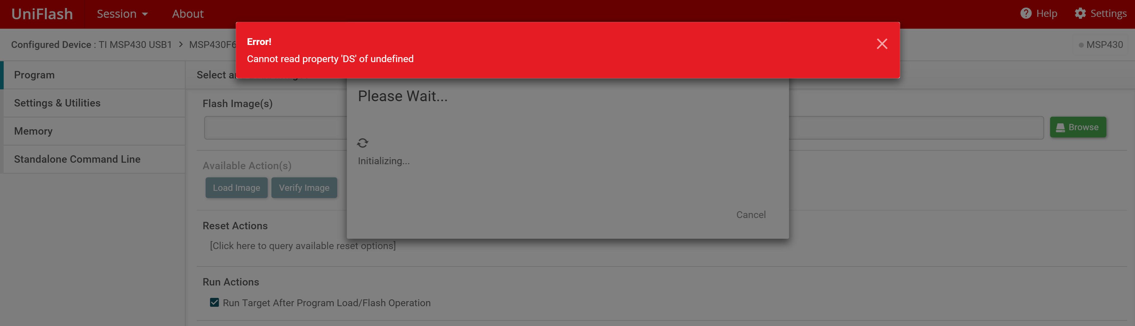
I haven't used my black MSP-FET in a while. Yesterday I plugged it into my Windows 10 PC and launched CCS10, and was told the programmer needed a firmware update. At first, the update has failed, leading me to ditch the USB hub that the device was originally connected through. The second time it seemed to have gone fine, after a minute or two, I was brought back to the main screen without any confirmation of update success.

After the update, my device has started acting weird. Upon connecting the device, the green "Power" LED turns ON, and the device is unresponsive. After exactly 30 seconds, the green LED turns OFF, the red "Mode" light turns ON. When I try to debug my target board (a custom board with a MSP430F5522), the CSS throws an error "unknown device". I confirm the board is good because I was able to successfully debug the board using another FET device I normally use.

Upon reading the user guide for FET, the "red LED ON, green LED OFF" scenario often occurs when the target Vcc is erroneous, or the USB cable is defective. My situation is strange because I get to this state without having the FET connected to target devices. I made sure my USB cable was good by connecting to and using the other FET device I normally use.

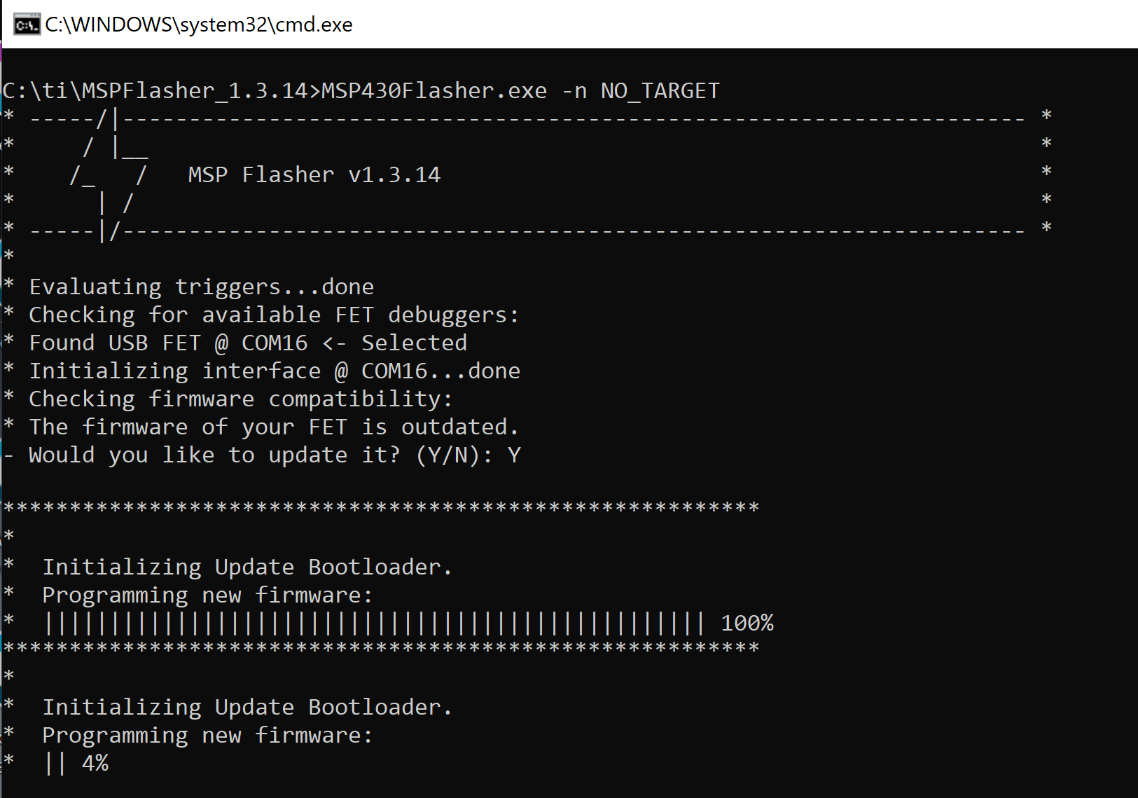
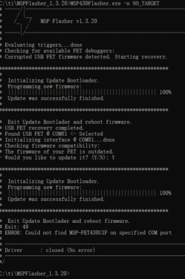
In order to identify the issue, I used MSP Flasher V1.3.20. It seems like the PC recognized the FET device, is able to confirm the firmware is up-to-date while the FET is in "error" state, but is either not able to provide Vcc to the target (error 44), or is not able to recognize the device (error 16). 

Any suggestions on how to fix the FET device, or how can I further isolate the issue, is greatly appreciated.

Thank you!

Wenbo

  • Hello Wenbo,

    Thanks for your detailed post. Let me check with our Tools team. It may be Friday or early next week until I can get back to you. Thanks for your patience.

    In the meantime, could you please share the serial numbers for both the working and non-working MSP-FET's?

    Regards,

    James

  • Hello James, 

    The working one is 141200485, while the non-working one is 140700727.

    Thank you,

    Wenbo

  • Thanks for sharing that, Wenbo. I'm still waiting on our Tools team. I'll let you know when I hear back from them.

    Regards,

    James

  • As a follow-up, are you using SBW on your custom F5529 board?

    Regards,

    James

  • Hi James,

    No. I am using 4-wire JTAG

    Thanks,

    Wenbo

  • Hi Wenbo,

    Thanks for confirming.

    Wenbo Gong said:
    leading me to ditch the USB hub that the device was originally connected through.

    Unfornately, USB hubs can cause issues with the MSP-FET. Can you try installing UniFlash and try to program your custom board? Hopefully, UniFlash will try to update the MSP-FET. If there's a recovery option that pops up along with the update option, try clicking the recovery option. Make sure other programs that would use the MSP-FET (e.g. Flasher, CCS) are closed and all other MSP-FET or debuggers are disconnected. Use a USB2 port if possible too.

    Let me know if that works.

    Regards,

    James

  • What's strange is that another user saw the same 44 error when using MSPFlasher v1.3.8 but was able to update their MSP-FET using MSPFlasher v1.3.19.

    CCS/MSP-FET: mspflasher error 44 Could not set device Vcc

    Regards,

    James

  • Hi, I connected my bad FET to the laptop USB port, and selected by chip of F5522. I don't have a hex file to program it with, so I pressed on "Reset Actions" in order to have FET speak to my board.

    Two times when I clicked on it, I received two different errors. One is "FET already in use" another time "Unknown Device".

    Please advise.

    Thank you,

    Wenbo

  • Hi James,

    Thanks for the insight. I see the conclusion from the other post was: use MSP Flasher v1.3.19 and not v1.3.8. As stated above, My Flasher version is 1.3.20. 

    Should I downgrade the flasher to 1.3.19 and try to connect again?

    Were you able to get more feedback regarding the UNIflash software?

    Thanks,

    Wenbo

  • Hi Wenbo,

    Wenbo Gong said:

    Hi, I connected my bad FET to the laptop USB port, and selected by chip of F5522. I don't have a hex file to program it with, so I pressed on "Reset Actions" in order to have FET speak to my board.

    Two times when I clicked on it, I received two different errors. One is "FET already in use" another time "Unknown Device".

    Thanks for the update. I tried this using UniFlash, but I got a different error. If you try using UniFlash to update the MSP-FET, I would recommend programming the target with .out or .txt file. Those can be generated in CCS and found under the Debug folder in the CCS project folder. UniFlash is somewhat easier to use than MSP Flasher, so I thought it'd be a quick test. Let's shift back to MSP Flasher.

    Wenbo Gong said:

    Thanks for the insight. I see the conclusion from the other post was: use MSP Flasher v1.3.19 and not v1.3.8. As stated above, My Flasher version is 1.3.20. 

    Should I downgrade the flasher to 1.3.19 and try to connect again?

    So, I installed both MSP Flasher v1.3.14 and v1.3.20 on my PC. Using v1.3.20, I executed the "MSP430Flasher.exe -n NO_TARGET" command with my MSP-FET connected. After this command, MSP Flasher discovered that the MSP-FET firmware was outdated. After entering "Y", the firmware was updated successfully. Executing this command again did not trigger the firmware update message.

    Now, I did the same thing using v1.3.14. After the "MSP430Flasher.exe -n NO_TARGET" command, I got a message saying the firmware was "outdated" even though it was the latest - that's because it didn't match the version that comes with v1.3.14. I entered "Y", and the firmware was updated (actually downgraded) to the version that comes with v1.3.14.

    You can choose to use a different version besides v1.3.14. I just wanted to use an earlier one to see if I could upgrade and downgrade consistently which I was able to do. Please try this and let me know if it helps fix the issue.

    The next thing we could try to do is restore the MSP-FET. 

    Regards,

    James

  • Hi James,

    I was able to install V1.3.14 alongside V1.3.20. Upon using the "NO_TARGET" command, I was prompted to "update" the firmware just like you experienced. Once the update is almost finished, I was prompted that the update failed, and I chose "Retry". The software then prompted that the update was successfully finished, and the FET firmware is up to date. 

    At this point, the LED situation is the same as before: red LED on, green LED off. I unplugged and replugged the FET, that did not resolve the issue.

    Although your suggestion did not resolve the issue, I hope this has brought us one step closer to the solution.

    Thanks,

    Wenbo

  • Hi Wenbo,

    Thanks again for trying that. I agree that it does seem like small progress. I have a few follow-up questions.

    1. Can you please share your JTAG circuitry schematic? I'd like to check those connections and components.

    2. Is there a chance that your custom board draws more current than the maximum recommended supply current of 60 mA through pin 2 of the 14-pin JTAG connector? If so, perhaps that's damaged something in the MSP-FET. Otherwise, I'd recommend using an external power supply for high current requirements.

    3. Can you please try the recovery process described in Section 5.6.5.3 MSP-FET HID Cold Boot in the MSP Debuggers User's Guide?

    Regards,

    James

  • Hi James,

    1. JTAG connection schematics is attached. We've connected the 3.3V pin to the VBus pin on the chip as well.

    2. When the current draw is 30mA with the power draw of 0.26W under normal operation.

    3. I attempted the recovery mode. Both CCS and MSP Flasher prompted me to recover the firmware, and claimed to have successfully finished the process. However, the device is still at "red LED on, green LED off" state, 30 seconds after boot.

    Seems like we need more ideas! haha...

    Thank you.

    Wenbo

  • Hi Wenbo,

    Thanks for the additional details. I have a few follow-up questions to help me better understand your configuration.

    Wenbo Gong said:
    1. JTAG connection schematics is attached. We've connected the 3.3V pin to the VBus pin on the chip as well.

    Thanks for sharing. The connections between the MSP430 and the POGO connector look correct, but they don't match the names in the POGO connector. I'm not sure if those are typos or what, so I'm not sure how those pins are connected to the MSP-FET. Could you please fill in the following table? You can find the MSP-FET pin #'s and descriptions underneath the MSP-FET.

    I think you're saying that you're using the MSP-FET Pin 2 to power the board and that's connected to DVCC on the device, but please confirm. What is JP5? Do you connect the MSP-FET connector there? We use 14-pin connectors for the MSP-FET, but this one has 10 pins.

    Net MSP-FET Pin #
    TEST/VPP
    RST
    TCK
    TMS
    TDI/VPP
    TDO/TDI
    DVCC Pin 2

    Wenbo Gong said:
    2. When the current draw is 30mA with the power draw of 0.26W under normal operation.

    I'm sorry but this isn't clear. If DVCC is 3.3 V and the power draw of the board is 0.26 W, then the current draw is ~79 mA, not 30 mA. That's greater than the recommended limit of 60 mA. Can you please clarify?

    Wenbo Gong said:
    3. I attempted the recovery mode. Both CCS and MSP Flasher prompted me to recover the firmware, and claimed to have successfully finished the process. However, the device is still at "red LED on, green LED off" state, 30 seconds after boot.

    Thanks for trying that. The red LED typically indicates excessive current is or has been supplied to the target through Pin 2 or through the JTAG wires if Pin 4 hasn't been connected to sense an external supply if that's used instead of Pin 2. Because we've gone through the restore and recovery processes with no luck, I'm getting concerned that the MSP-FET has been damaged by excess current.

    Regards,

    James

  • Hi James,

    Let me clarify and correct myself.

    1. I misremembered the DVCC wiring. Previously I took power from VCC on FET pin 2 and feed it to a VBUS pin on MSP430F5522. But now I don't do that anymore, and just use the 6 pins from FET.

    Net FET
    TEST/VPP 8
    RST 11
    TCK 7
    TMS 5
    TDI/VPP 3
    TDO/TDI 1
    GND 9

    2. I mentioned "typical operating power" of 0.26W was based on my 9V battery supplying it. This converts to a current of 30mA across the board.

    3. I couldn't think of why there would be excess current between FET and my board, given that the FET supplies power to the board during programming.

    If the FET is indeed damaged, what would be a good way to get it fixed? Can I send in the device and have the technicians repair it?

    Thank you,

    Wenbo

  • Hello Wenbo,

    Thanks for the additional details.

    Wenbo Gong said:
    1. I misremembered the DVCC wiring. Previously I took power from VCC on FET pin 2 and feed it to a VBUS pin on MSP430F5522. But now I don't do that anymore, and just use the 6 pins from FET.

    If you're using external power to your device, then Pin 4 (VCC_TARGET) must be connected to your external DVCC to sense the logic levels. If it's not connected, this could trigger the Red LED to stay on due to excess current being drawn over the JTAG wires.

    Wenbo Gong said:
    2. I mentioned "typical operating power" of 0.26W was based on my 9V battery supplying it. This converts to a current of 30mA across the board.

    This makes more sense. However, the current consumption may be higher than 30 mA in the 3.3 V power domain due to the power conservation theorem. This isn't a concern when powering externally but still is if the MSP-FET was used to provide this power before the issue happened. I would measure the current draw to the DVCC pin at 3.3 V to get an accurate current consumption value.

    Wenbo Gong said:
    3. I couldn't think of why there would be excess current between FET and my board, given that the FET supplies power to the board during programming.

    Please see my earlier comments.

    Wenbo Gong said:
    If the FET is indeed damaged, what would be a good way to get it fixed? Can I send in the device and have the technicians repair it?

    If the MSP-FET is truly damaged, then we recommend that you purchase a replacement. Unfortunately, we are unable to repair them.

    Regards,

    James

  • Thank you for the comments, James.

    At this point, I also believe the board is damaged, and it is unfortunate that it can't be fixed.

    I'll go ahead and order a new one.

    Best,

    Wenbo

**Attention** This is a public forum