This thread has been locked.

If you have a related question, please click the "Ask a related question" button in the top right corner. The newly created question will be automatically linked to this question.

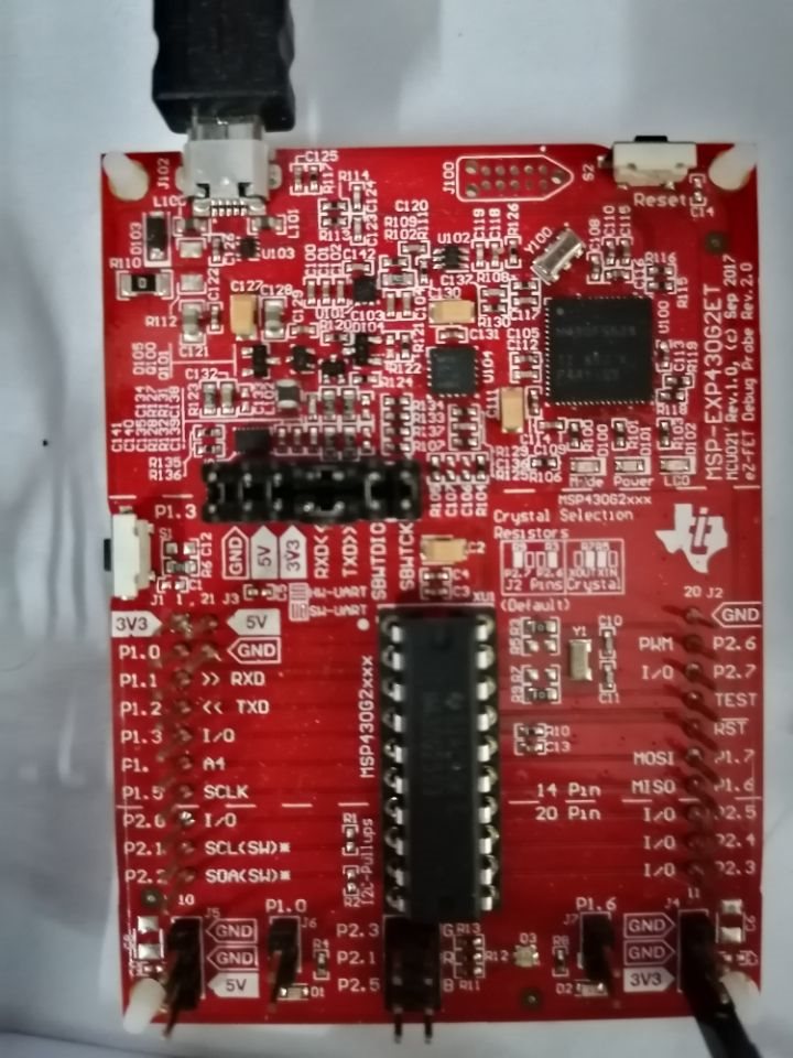
MSP-EXP430G2ET: How to set P1.1(RXD) and P1.2(TXD) as GPIO?

Part Number: MSP-EXP430G2ET
Other Parts Discussed in Thread: ENERGIA, MSP430F5529, MSP-EXP430F5529LP

I have been searched for answers in this forum.

Adding codes like "P1SEL &=~BIT1; P1SEL2 &=~BIT1;" didn't work.

 I need to use Serial monitor. If I remove the TXD and RXD jumpers,the Serial monitor in Energia has no response.

Anyone has an idea how to solve this problem?

  • If you're using the Energia (hardware) serial monitor, you don't want to use P1.1/P1.2 as GPIOs, rather as UART (USCI). As far as I know, Energia sets the PSEL bits properly, so you don't need to touch them. In this case, the TXD/RXD jumpers do need to be installed appropriately (90 degrees rotated from the others).

    I'm not quite sure what you want to accomplish.

  • Thanks for your answer,I mean that  I want to use P1.1/P1.2 as GPIOs.

    I use a sensor that need to connect GPIO to check other Pins in launchpad.      P1.6/P1.7 work well(don‘t need to change the code,just rename “#define  ...”)

    Only P1.1/P1.2 can not work.     What should I do?

  • Stating the obvious: You can't use P1.1/P1.2 for the UART (Serial Monitor) and for GPIO simultaneously. If you want to use them for GPIO, you need to remove the TXD/RXD jumpers, since otherwise the Backchannel UART (USB side of the "dotted line") will get in your way.

    Is there a reason you need to use P1.1/P1.2 for your purpose rather than some other (unused) pins? Maybe it would help if you can explain what your sensor does.

  • In fact,I use P1.1/P1.2 for GPIO in order to set software SPI. Other GPIOs have used for other sensor. I know P1.1/P1.2 can be used for hardware SPI, but the "SPI.h"  in Energia is suited for P1.6/P1.7(UCB0).

    And I try to change the "SPI.h" code, but it didn't work.  Today I know that UART and SPI can not be used for the same pins  simultaneously.

    I think there are some ways to solve it:1.change the IDE,don't use Energia;  2.GPIO Expander; 3.Find a way instead of Serial Monitor function.

    Do you have better idea?  Thanks a lot !

  • Hardware SPI can be done on either P1.1/2/4 (UCA0, which can also be a UART) or P1.5-7 (UCB0, which can also be I2C). 

    Software SPI can be done on pretty much any three pins, e.g. P2,0-2. Are you writing it yourself, or using a package from somewhere?

  • Software SPI code: from github; Hardware SPI code: Energia "SPI.h".

    You mean I can use P1.1/P1.2 for the UCA0 and the UART(Serial Monitor)  simultaneously?

    What about use GPIO Expander like 74HC595? Since I have only one GPIO can be used now.

    Other pins like P2,0-2 have been used for software I2C.

  • You can't use UCA0 for SPI and UART simultaneously.

    You didn't mention that you had run out of pins. The photo doesn't show any connections at all (except for UCA0(UART) through the TXD/RXD jumpers).

    If you've truly used all your pins I guess you'll have to find an expander; a 595 shift register might serve, but first count the number of pins you'll need to control it. Since you're already using I2C, there are I2C-based GPIO expanders which won't cost you any pins at all.

    Keep in mind that I2C is a multidrop bus. If you have more than one I2C device you can chain them together without using any additional pins.  

  • You help me a lot ! I misapprehend  that software I2C couldn't be a multidrop bus.

    Unfortunately,  the Non-volatile memory of G2553 can't bear too many sensor and their codes. The energia says "region 'rom' overflowed by 1218 bytes".

    I try to reduce unimportant code and want to add extern flash.

    Finally I decide to buy a new launchpad with more pins and more Non-volatile memory  :)

  • Sounds like a wise choice. Running out of resources right at the beginning is usually a warning sign (:-)).

  • I got MSP430F5529LP yesterday. Serial Monitor can not  receive any message. After trying something, I can't find the way.

    So, once again come to here.

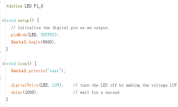
  • What code are you running? If you haven't already, try a sketch that just writes to the Serial Monitor.

    The pins on the MSP430F5529 are quite different from the G2553. Are you using the Arduino(-ish) pin names, or referencing the pins directly?

  • I use Energia IDE. And it is suit for almost MSP430 board as long as choose correct type in menu bar.

    G2553 and F5529 run the same code, G2553 can see the messenger in  the Serial Monitor.

    I guess that USB mode and TXD/RXD have conflict in F5529.

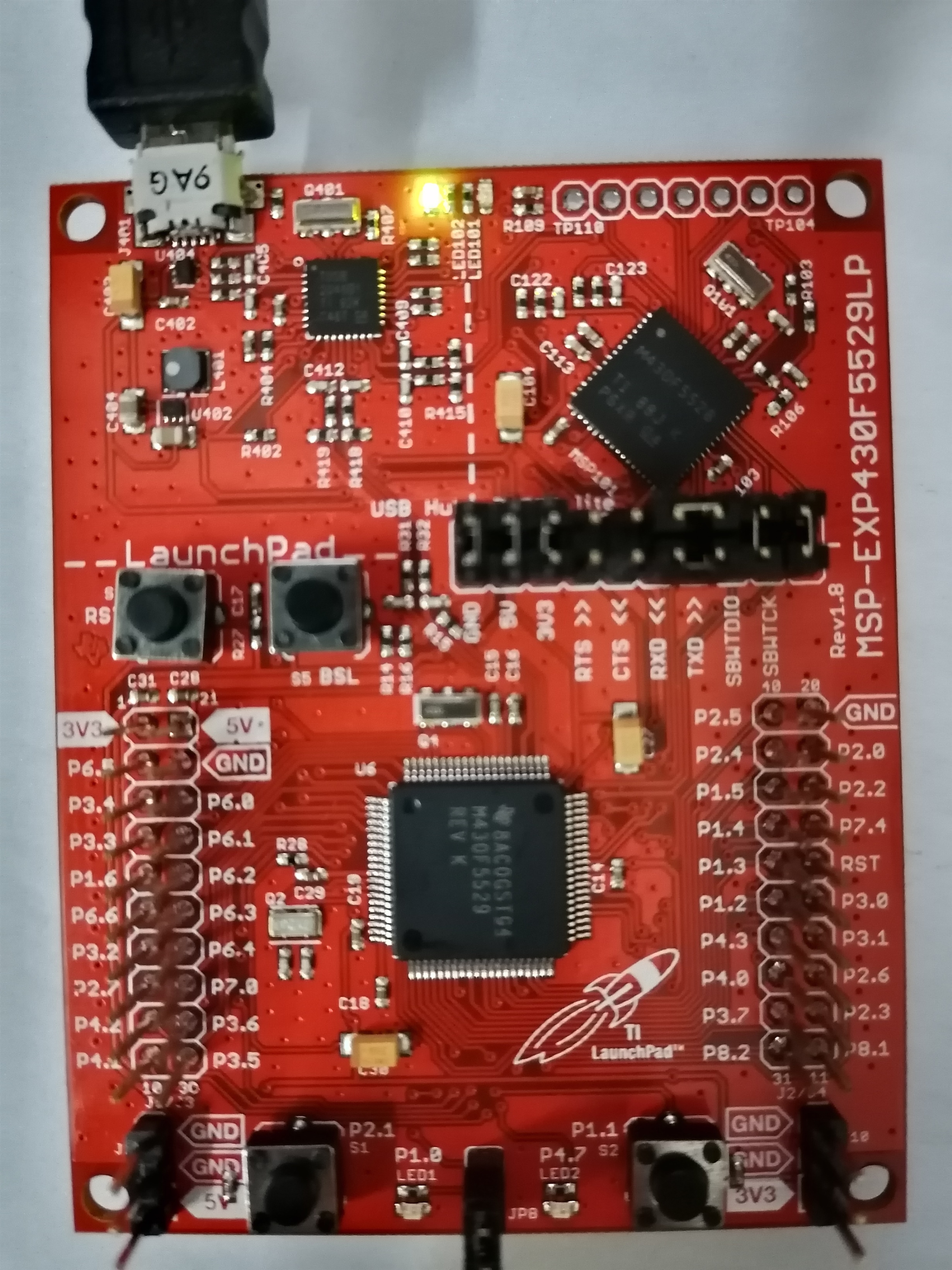
    Figer1. F5529 launchpad

    Figer2. Serial Port ,both set 9600

    Figer3. running code

    By the way, when I use F5529 first time, new disc show up. And next time, I don't see it again.

  • The RXD/TXD jumpers should Not be rotated on the MSP-EXP430F5529LP., rather they should be installed parallel to the other jumpers.

    The rotation thing is only done on the G2[ET] Launchpad. (It's an accommodation to the Software UART.)

  • It's my fault. I remember  I installed them parallel to the other jumpers.But it didn't work.

    And this time can work. Thank,guy.

**Attention** This is a public forum