This thread has been locked.

If you have a related question, please click the "Ask a related question" button in the top right corner. The newly created question will be automatically linked to this question.

MSP432P4111: MSP432: SPI clock breaking bits and MOSI bits half speed of CLK

Part Number: MSP432P4111

Hi,

I'm using an MSP432P4111 to Tx SPI data using the DMA. I'm attempting to send data out at 12.5MHz CLK speed for the SPI clock (time for each bit), but at seeminly random times in the send, there is a bit or two of stretching or missed bit stepping out. I've walked my code back to a pretty simple setup, and I'll share the few sets of code I have.

My DMA code:

    /* Configuring DMA module */
    DMA_enableModule();
    DMA_setControlBase(controlTable);
    int b;
    for(b = 0; b < 64; b++)
        data_array[b] = b;
    /* Setting Control Indexes. In this case we will set the source of the
     * DMA transfer to our random data array and the destination to the
     * CRC32 data in register address*/
    DMA_setChannelControl(UDMA_PRI_SELECT,
            UDMA_SIZE_8 | UDMA_SRC_INC_8 | UDMA_DST_INC_NONE | UDMA_ARB_1024);
    DMA_setChannelTransfer(UDMA_PRI_SELECT,
            UDMA_MODE_BASIC,
            data_array,
            (void*) SPI_getTransmitBufferAddressForDMA(EUSCI_B2_BASE),
            1024);
    /* Assigning/Enabling Interrupts */
    DMA_assignInterrupt(DMA_INT1, 0);
    Interrupt_enableInterrupt(INT_DMA_INT1);
    Interrupt_enableMaster();

    /* Enabling DMA Channel 0 */
    DMA_enableChannel(0);

    FRAM1_CS_OUT |= FRAM1_CS_BIT;
    FRAM1_CS_OUT &= ~FRAM1_CS_BIT;
    /* Forcing a software transfer on DMA Channel 0 */
    DMA_requestSoftwareTransfer(0);
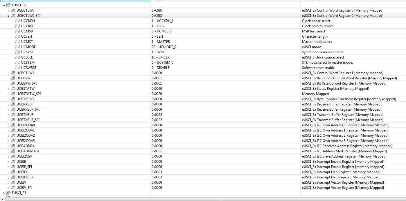
My SPI setup code:

void init_SPI( void )
{
	// set up SPI port pins
	SPI_SEL0  |=  (SPI_MISO | SPI_MOSI | SPI_CLK);				// enable the special function on MISO, MOSI, CLK pins
	SPI_SEL1  &= ~(SPI_MISO | SPI_MOSI | SPI_CLK);				// enable the special function on MISO, MOSI, CLK pins
//	SPI_DIR  |=  (SPI_MOSI | SPI_CLK);							// set MOSI, SLK as outputs
//	SPI_DIR  &= ~(SPI_MISO);										// set MISO as input

	// set up SPI control registers
	SPI_CTLW0  = (EUSCI_A_CTLW0_UCSSEL_2 | UCSWRST);								// hold port in reset, BRCLK = SMCLK
	SPI_CTLW0 |= (UCMST | UCSYNC | EUSCI_A_CTLW0_MODE_0 | UCCKPH | UCCKPL/*| UCMSB*/ );	// Master Mode, Synchronous Mode, 3-Pin SPI, CPH = 1, CPL = 0, LSB first
//	SPI_BRW = (Uint16)( /*SMCLK_HZ somethings not working right on this macro call...*/ / SPI_BAUD_DEF);					// load baud default rate
	SPI_BRW = 1;

	SPI_CTLW0 &= ~UCSWRST;											// initialize eUSCI SPI State Machine

	// set up SPI interrupt registers
	SPI_IFG  &= ~(UCTXIFG | UCRXIFG);								// clear rx/tx interrupt flags
	SPI_IE	&= ~(UCTXIE | UCRXIE);									// set rx/tx interrupt enable
}

And my clock setup:

    /* Configuring pins for peripheral/crystal usage and LED for output */
    GPIO_setAsPeripheralModuleFunctionOutputPin(GPIO_PORT_PJ,
          GPIO_PIN0 | GPIO_PIN1 | GPIO_PIN2 | GPIO_PIN3, GPIO_PRIMARY_MODULE_FUNCTION);

    /* Setting the external clock frequency. This API is optional, but will
     * come in handy if the user ever wants to use the getMCLK/getACLK/etc
     * functions
     */
    CS_setExternalClockSourceFrequency(32768,48000000);

    /* Starting HFXT in non-bypass mode without a timeout. Before we start
     * we have to change VCORE to 1 to support the 48MHz frequency */
    PCM_setCoreVoltageLevel(PCM_VCORE1);
    FlashCtl_A_setWaitState(FLASH_A_BANK0, 2);
    FlashCtl_A_setWaitState(FLASH_A_BANK1, 2);
    CS_startHFXT(false);
    CS_startLFXT(false);

    // Assert the frequencies of MCLK, ACLK, HSMCLK, and SMCLK
    CS_initClockSignal(CS_MCLK, CS_HFXTCLK_SELECT, CS_CLOCK_DIVIDER_1);			// MCLK   - 48MHz crystal
	CS_initClockSignal(CS_ACLK, CS_LFXTCLK_SELECT, CS_CLOCK_DIVIDER_1);			// ACLK   - 32.768 kHz watch crystal
	CS_initClockSignal(CS_HSMCLK, CS_HFXTCLK_SELECT	, CS_CLOCK_DIVIDER_1);		// HSMCLK - 48MHz
    CS_initClockSignal(CS_SMCLK, CS_HFXTCLK_SELECT, CS_CLOCK_DIVIDER_4);		// SMCLK  - 48/2 = 24 MHz		-	datasheet says max 24MHz for UART/SPI/I2C input clock

I'm using this on the MSP-EXP432P4111 Launchpad, and I"ve tried two boards (one was brand new) and the same phenomenon is happening there too. I'm using the standard 48MHz crystal for my clocks, while dividing the SMCLK down to <24MHz (I saw another post that said to stay below 16MHz, so this should still be ok I think).

My Logic Analyzer is also showing me that the gap between bits is consistently at 1us apart - the box on the right shows the time between the two Vertical lines. I've attached that as well.

Let me know if there's any info I can provide that would help understand my problem.  Thanks for the help on this,

  • You appear to be feeding the SPI with a non-triggered software DMA transfer using channel 0 (SRC 0). This will overrun the SPI transmitter, which will cause "erroneous transmission" [Ref TRM (SLAU356I) Sec 25.3.8.1].

    To have the SPI unit (TXIFG) trigger the DMA, you need channel 4 with SRC 2 (EUSCI_B2_TX0)  [Ref data sheet (SLASEA0) Table 6-37]. You would set this with something like:

    > MAP_DMA_assignChannel(DMA_CH4_EUSCIB2TX0);

    and then you need to use that channel number to call MAP_DMA_setChannelControl and MAP_DMA_setChannelTransfer. 

    I recommend reading through example dma_eusci_spi_loopback:

    http://dev.ti.com/tirex/explore/node?node=AKlQzYdbln2x6dc7mdgcEQ__z-lQYNj__LATEST

  • I don't know if that fixes this. I tried making my setup the same as the example, but only using the EUSCIB2TX0 portion. But there's no DMA transfer happening and its the same when I use the software DMA trigger and with just MAP_DMA_enableChannel(4); I don't know if I need to send the first byte of the SPI Tx manually, and when I try that, it only sends a few bits of the first byte and stops.

    Here's my new code:

        /* Configuring DMA module */
        DMA_enableModule();
        DMA_setControlBase(MSP_EXP432P401RLP_DMAControlTable);
        int b;
        for(b = 0; b < 64; b++)
            data_array[b] = b;
        /* Setting Control Indexes. In this case we will set the source of the
         * DMA transfer to our random data array and the destination to the
         * CRC32 data in register address*/
        DMA_assignChannel(DMA_CH4_EUSCIB2TX0);/* Assign DMA channel 0 to EUSCI_B0_TX0, */
    //    DMA_setChannelControl(UDMA_PRI_SELECT,
    //            UDMA_SIZE_8 | UDMA_SRC_INC_8 | UDMA_DST_INC_NONE | UDMA_ARB_1024);
        DMA_setChannelControl(DMA_CH4_EUSCIB2TX0 | UDMA_PRI_SELECT,
        UDMA_SIZE_8 | UDMA_SRC_INC_8 | UDMA_DST_INC_NONE | UDMA_ARB_1);
    
        DMA_setChannelTransfer(UDMA_PRI_SELECT,
                UDMA_MODE_BASIC,
                data_array,
                (void*) SPI_getTransmitBufferAddressForDMA(EUSCI_B2_BASE),
                26);
        /* Assigning/Enabling Interrupts */
        DMA_assignInterrupt(DMA_INT1, 4);
        MAP_DMA_clearInterruptFlag(DMA_CH4_EUSCIB2TX0 & 0x0F);
        Interrupt_enableInterrupt(INT_DMA_INT1);
    //    Interrupt_enableMaster();
    
        FRAM1_CS_OUT |= FRAM1_CS_BIT;
        FRAM1_CS_OUT &= ~FRAM1_CS_BIT;
        /* Enabling DMA Channel 4 */
        DMA_enableChannel(4);
    
    
    //    EUSCI_B2->TXBUF = 0x06; 

    This is how I have the control table defined now, in case this is what is wrong:

    /* DMA Control Table */
    #if defined(__TI_COMPILER_VERSION__)
    #pragma DATA_ALIGN(MSP_EXP432P401RLP_DMAControlTable, 1024)
    #elif defined(__IAR_SYSTEMS_ICC__)
    #pragma data_alignment=1024
    #elif defined(__GNUC__)
    __attribute__ ((aligned (1024)))
    #elif defined(__CC_ARM)
    __align(1024)
    #endif
    static DMA_ControlTable MSP_EXP432P401RLP_DMAControlTable[32];

    My apologies, I'm still trying to learn how to use this DMA. It seems to be more complicated than another DMA I've used. 

  • >    DMA_setChannelTransfer(UDMA_PRI_SELECT,

    You also need the channel number here. Try:

    >        DMA_setChannelTransfer(DMA_CH4_EUSCIB2TX0 | UDMA_PRI_SELECT,

  • Thanks, but that didn't solve the problem. My SPI Tx still is breaking up. Here's some pictures of the state of things now:

    And closer in:

    I seem to think the DMA portion might be right now, but this SPI issue is still here. I currently have the HFXT sourcing both the MCLK and SMCLK (SMCLK at 12.5MHz for SPI), but I'll try setting up the DCO for 10MHz and see if it just may be too fast. 

  • One thing that nags at me is that the data seems to be coming out MSbit-first, even though you've set UCMSB=0. That makes me wonder whether the SPI configuration really looks the way we think it does. It might be worth pausing in the debugger and checking the actual settings [Register view].

  • The LSB might be because I pullled it back to my previous settings. Here's my SPI registers in the DMA interrupt (after its sent):

    I noticed a huge improvement in DMA transfer behavior when I went from DMA_AUTO to DMA_BASIC, so that's good. But I'm seeing this strange uneven clock behavior that goes away when I slow the clock below ~6MHz (I think I begin to see a completely normal, 50% duty cycle clock at 4MHz). The SPI protocol in my logic analyzer is decoding exactly what I'm sending. I could leave this as it is, but I'm still a bit hesitant to believe this will actually work with external chips. 

    Here's my current SPI transfer in the logic analyzer. Its set to 12MHz clock speed. I just don't like that non-50% duty cycle, but if it works with the chip im talking to, I guess I'll go with it. Looking for thoughts on this. Thanks,

  • Most SPI devices have a minimum clock frequency specification of 0. So pauses in the SPI clock are not going to cause any trouble so long as the data setup and hold times are met.

  • I was thinking this might be the case. I'll report back when I get the chip in and see if I read back what was written. Then We'll know if this setup will work. 

  • Unsolicited: The SPI FRAM chips I've worked with used mode=0 or 3, where this code uses mode 2. (But trust your data sheet, not me.)

  • That's a good point - we might be using the same chip - mine says that too. I actually forgot to verify that.

    I've just been worried about whether the bytes are coming across correctly and the speeds of the clock and transmission. I've just been sending SPI comms out to nothing (the un-connected pins on the eval board) and reading it in on my logic analyzer. I wonder if that could be making the clock appear distorted because its not connected to another SPI chips internal circuitry? 

    I guess I'll find out when the chip comes in next week.

  • Hi 

    Have you get the device and have check about the result?

  • Not yet. There were delays in getting a board ordered and also made. I think I'm one week away from being able to verify this.

  • Ok, we will wait for you.

**Attention** This is a public forum