This thread has been locked.

If you have a related question, please click the "Ask a related question" button in the top right corner. The newly created question will be automatically linked to this question.

MSP430G2553: Clocking options to achieve acceptable error at standard UART baud rates

Part Number: MSP430G2553

In trying to assure error free communication at 115200 baud for the USCI (UART mode), its not clear on options for clocking this device. We also need help in interpretation of UG table 15-4 and 15-5

The DCO table (pg 30 of the datasheet (SLAS735J)) shows +/-3% error across temperature. Added to the digital error shown in tables 15-4 and 15-5 of the user guide (SLAU144J) of -0.8/+0.6%, or 0/+1.6% (depending on over sample mode), we get an accumulated error of ~35% of a bit-time (start + 8 data + parity + stop). This may be OK for an ideally clocked device at the opposite end of the line. However it seems to imply two 'G2xx3 devices may have an issue (assuming they're off in opposite directions).

Three questions ...

1. For UG table 15-4 and 15-5 is that error expressed as "%-of-a-bit accumulated across the whole character"? (we *think* thats what the preceding paragraph is trying to state)

2. Is the ~35%-of-a-bit error across a character stated above correct?

3. If so, what is the solution for clocking this device in a way that allows UART to UART between two 'G2xx3? (HF mode not supported by LFXT1, and LF mode is not characterized (presumably not supported) for crystals other than 32768)

Thanks ... Jim

  • Two options:

    An external oscillator of 1.843MHz is an option I think.

    Use the 32KHz LFXT to control the DCO.

  • David,

    So add an oscillator I get (that'll cost roughly 50% the cost of the MSP).

    But by "use 32KHz LFXT to control the DCO", do you mean use 32.768KHz, or that I can use a crystal with a value that will multiple up to give the exact frequency I need in order for SMCLK to be exactly 16X the baud rate?

    In the former case (32.768KHz crystal), table 15-4 of the UG shows very high error at 9600 baud and implies you can't go higher. In the later case (crystal other than 32.768KHz), the DS shows only 32768 as the "typ" crystal value, implying no other value has been characterized?

  • TI has, or at least had, a document somewhere that described how to build a software Frequency Locked Loop using the LFXT and DCO. Basically you use one timer to count MCLK and accumulate the count. The other timer runs from ACLK/LFXT. Periodically, based on ACLK, you examine the total count from the DCO. Twisting the knobs on the DCO as required if it is out of line.

  • I expect David is referring to Example msp430g2xx3_dco_flashcal.c, which (as written) re-computes the DCO constants using ACLK (nom. 32kHz crystal)  as a reference, and writes them to InfoA. 

    http://dev.ti.com/tirex/explore/node?node=APXSlUhYWYfUi-lBT1UjXA__IOGqZri__LATEST

    The technique is effectively an FLL using Capture from ACLK (CCI0B), but it's invasive, so you'd need to find a way to integrate it with what you're using the timers for.

  • No, I am referring to slaa336. It took a while to dredge that one up from my memory as it has been a while since I used it.

  • Thanks guys, adding the crystal and performing the calibration periodically seems like a viable solution for us.

    No response from TI on interpretation of those tables. For us non-Tier1 customers we use to see a face from TI on occasion, or at least had a path back to the factory via the dist'ys FAEs. At this point I'm worried about even online support. 

  • Hi ,

     Is the ~35%-of-a-bit error across a character stated above correct? No

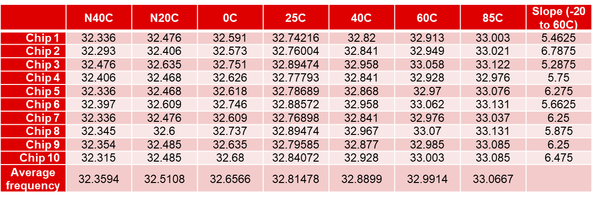
    Here is the result of internal crystal tested on FR4133, you can take it at a reference. The things is that, if the temperature is same, the frequency error between two device will be less than -0.8/+0.6%, or 0/+1.6% . From my point of view, -0.8% happens at -40C, +0.6% happens at 85C.

    But if you want to get a high accuracy clock, you should not choose internal crystal. Or you can use a same clock signal to control two device. By the way, if the UART baud rate has less than 3.75% error, the communication is stable.

    Sorry, recently, I am really exhausted with offline customer support and internal business.

    Eason

  • Eason,

    In our case the two points on an RS485 connection could be a widely varying temperatures. Its an airborne system with one unit in a conditioned area near the operator and the second subject to the external environment. The delta could be 40-50C.

    So in looking at the possible error I want to be sure I understand the TI information correctly. The -0.8/+0.6 (or 0/+1.6%) I *believe* are accumulated error across a character due to the fact the base-10 DCO frequency cannot be made to match the 115200 exactly; while the DCO error (~ +/-3%) will accumulate across the character. Hence my thought that total error is roughly [(3% x 11-bits) + 1.6%], again, with an assumption that the MSP is communication with a perfect, 0% error, 115200 baud source. Does this seem correct? and if not, what is the correct way to view these two sources of error?

    Thanks ... Jim

  • 11 bits is a bit long. The important sampling times occur at the center of the start bit and the following 8 data bits. So that would be 8.5 bit times. (The stop bits are examined but if you aren't checking for framing errors then they don't matter anyway.)

**Attention** This is a public forum