This thread has been locked.

If you have a related question, please click the "Ask a related question" button in the top right corner. The newly created question will be automatically linked to this question.

MSP430FR6047: Ultra Sonic Design Center ADC Capture result floating above zero

Part Number: MSP430FR6047
Other Parts Discussed in Thread: MSP430FR6043, TIDA-01486

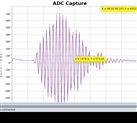
I have a homemade sensor design mounted on the outside of a 2" schedule 80 pipe.   Both sensors are on the top of the pipe. The signal passes into the pipe and then bounces off the bottom of the pipe, reflecting back up to the other sensor. I am getting very good signal quality with the PGA set at about 18 - 20. The issue is that the capture signal is always floating above 0. I have tried putting a couple of 1k resistors across the transducers with no noticeable result. I seem to get inconsistent results that are negated using the " Envelope Crossing Threshold" setting. Adjusting it to around 40 seems to help. Are the signal bias and abnormally high Envelope Crossing Threshold value related?

Also, on the Advanced Parameters there is an option called "Search Range". Where can I get some information of what that is?  I can't seem to find much on that, is it related to my issues?

Merry Christmas

  • Hi Garret,

    You should check in your project to enable DC_Offset_Cancellation if it's not already enabled. This is set by

    #define USS_APP_DC_OFFSET_CANCELLATION_ENABLE

    in your project. You should also ensure that

    #define USS_APP_DC_OFFSET_CANCELLATION_INTERVAL     (0)

    is set to some value other than zero (try 30). Although you won't see the offset correction in your capture, it should correct the error you are seeing in absolute time of flight. You should be able to find these two #defines in USS_App_userConfig.h.

    BR,
    Leo

  • On the Advanced Parameters there is an option called "Search Range". Where can I get some information of what that is?  I can't seem to find much on that, is it related to my issues?

    Where are you finding this information?? I am missing a key document?

    Thank you

    Garret

  • Hi Garret,

    You should take a look at the quick start guide:

    https://www.ti.com/lit/ug/slau810b/slau810b.pdf 

    If you look under the figure on page 9, you'll see that search range isn't used for water metering.  The same GUI is used for both gas and water metering. If you look at the quick start guide for gas metering with the MSP430FR6043, you'll see how this parameter is used for gas metering applications.

    BR,
    Leo


  • The USS_App_userConfig.h. and the #defines don't  seem to exist in the template examples. Can they be added. How does this algorithm work? Is it simply shifting all the data points up or down ? 

    Is my situation unusual? Do most signals look perfectly? What causes the signal to float above/below zero, are there any "rules of thumb" to avoid this?

    Garret

  • Hi Garret,

    There are several different possible reasons for why you are seeing an offset.(it's not unusual) The calculation of the mean offset can be found in:

    ussSwLibCalibration.c and can be optimized. Once the mean offset is calculated, all of the data points are shifted by this offset before processing.

    BR,
    Leo

  • What are some of those reason for the offset??

    I have tried placing resistors across the transducers, no significant difference.

    I am trying to understand why I am having this issue and many/most aren't.

    Is the averaging/offsetting process cpu intensive. Does it add significantly to the power usage?

    Garret

  • Hi Garret,

    The DC offset calculation can be performed infrequently(every 30 measurements) - so the extra overhead can be mitigated based on the interval. If your implementation requires a higher gain setting, the relatively small offset seen in lower gain setting implementations will be amplified. If you can increase your signal strength(and reduce your gain), you should see less of an offset. 

    BR,
    Leo

  • That makes sense. I am running the PGA at about 20 db. As the water warms up I need to raise the gain. I am using PVC pipe and I think it gets softer as the temp rises and is absorbing more of the signal.

    In the library there are 2 functions, USS_calculateOffsets and USS_estimateDCoffset(). They have identical descriptions.(This API allows the user to estimate the DC offset generated by the SDHS module) . Where/when do you use one as opposed to the other. The information is poor at best.

    Can you give me a better description?

    Garret

  • Hi Garret,

    If you search for USS_APP_DC_OFFSET_CANCELLATION_ENABLE in the code, you'll see that USS_estimateDCoffset() is called from the main (while) processing loop in USSLibGUIApp.c.  (the other function is not)  This DCoffset estimation is basically calculating the mean of UPS and DNS values - this mean is then subtracted from the ADC capture inside the algorithm before processing.

    // Add UPS and DNS captures based on configuration sample size
    for(i=config->captureConfig->sampleSize; i>0; i--)
    {
    upsSum+=(*pUpsValue++);
    dnsSum+=(*pDnsValue++);
    }

    // Store calibrated DC offset in configuration structures
    config->algorithmsConfig->calibratedDCOffsetDNS =
    (dnsSum/config->captureConfig->sampleSize);
    config->algorithmsConfig->calibratedDCOffsetUPS =
    (upsSum/config->captureConfig->sampleSize);

    BR,
    Leo

  • That is correct, but if you look at the template example for the 6005 chip they are using the other function.

    So, Where/when do you use one as opposed to the other?? Is there a better source/description of the various functions than this link?

  • Hi Garret,

    Unfortunately, there isn't exhaustive documentation on all of these functions. There is a lot of good information that can be found here:

    https://www.ti.com/lit/an/slaa837a/slaa837a.pdf 

    https://www.ti.com/lit/ug/slau732a/slau732a.pdf 

    BR,

    Leo


  • Hi,

    you can use the USS_APP_DC_OFFSET_CANCELLATION_ENABLE, just define it in the project properties 'predefined symbols'.

    You should also check the software which wil then be run. It shows that it will work reasonable for just 'one' set of transducers. I use three sets of transducers with additional hardware for switxhing and driving. If more than one set you should calibrate that required PWR-hardware! Basically I used an adapted version from the TIDA-01486 which uses a tremendous Opamp. For automatic calibration I implemented programmable resistors were adequate. 

    rgds.,

    Laurent van Poppelen


**Attention** This is a public forum