This thread has been locked.

If you have a related question, please click the "Ask a related question" button in the top right corner. The newly created question will be automatically linked to this question.

MSP430FR5872: LPM4.5 Wakeup

Part Number: MSP430FR5872

Hi Experts,

I am using LPM4.5 in my application and I am able to get proper LPM4.5 wakeup .

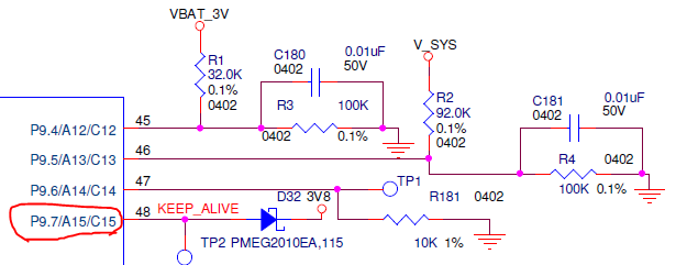
As per TI manual after wake-up from LPM4.5, the state of the I/Os are locked and remain unchanged until the application clears the LOCKLPM5 bit in the PM5CTL0 register. But the issue is when I clear this by PM5CTL0 &= ~LOCKLPM5;  I am seeing a glitch for my one of the GPIO pin on the oscilloscope. The following image discribe this behavior.

Can you explain the reason behind this and solution to avoid this.?

Thanks In Advance.


  • Hello Himanshu,

    Good question. Looking at your time scale, it seems as though there is a very slow RC-type decay from supply voltage. Do you have any captures that show this behavior on the pin with respect to when the interrupt signal is applied externally as well as with respect to when you clear the LOCKLPM5 bit?

    To help me debug this, would you please share the following information so that I can replicate your test setup:

    1. Which GPIO pin you are seeing this behavior on
    2. What the digital I/O register settings are before entry to LPM4.5 (PxOUT, PxDIR, PxREN, ect.)
    3. What the digital I/O register settings are after exit from LPM4.5 (or confirm they are the same as #2)
    4. What is the external circuit connected to the pin (any other devices/passives connected externally, or just the scope monitor?)

    Regards,
    Walter
  • Hi,

    1)The GPIO PIN which is showing this behavior is   P9.7 as configured as an output PIN as follwing

    #define ASIC_KEEPALIVE_PORT  &P9IN

    #define ASIC_KEEPALIVE_BIT      BIT7

    #define PXOUT_OFFSET    0x02

    #define PXDIR_OFFSET    0x04

    *((unsigned char *)ASIC_KEEPALIVE_PORT + PXDIR_OFFSET)      |= ASIC_KEEPALIVE_BIT;

    *((unsigned char *)ASIC_KEEPALIVE_PORT + PXOUT_OFFSET)      |= ASIC_KEEPALIVE_BIT;

    2) The  routine below  is used to enter into LPM4.5 mode:

    /* Configure P1.6 as an Interrupt*/

    P1IES |= BIT6;                                //P1.6 hi/low edge
    P1IFG = RESET_TO_ZERO;        // Clear all P1 interrupt flags
    P1IE |= BIT6;                                // P1.6 interrupt enabled

    STOP_WDT                                 //Disable watchdog before entering into LPM//

    PM5CTL0 &= ~LOCKLPM5;              // Disable the GPIO power-on default high-impedance mode to activate  previously configured port settings
    PMMCTL0_H = PMMPW_H;            // Open PMM Registers for write
    PMMCTL0_L |= PMMREGOFF;
    PMMCTL0_L &= ~(SVSHE);           //Disable high-side SVS
    PMMCTL0_H = RESET_TO_ZERO; // Lock PMM Registers

    /* Enter LPM4 Note that this operation does not return. The LPM will exit through a RESET event, resulting in a re-start*/
    __bis_SR_register(LPM4_bits);

    while (1) // MCU will wait here until the interrupt receive on P1.6
    {

    }

    After LPM4.5 wakeup :

    PM5CTL0 &= ~LOCKLPM5;                   // unlock GPIO 

    As soon as GPIO is unlock using above line then I am able to see that glitch.

    3)Please see below Image of Pin P9.7.

  • Thank you for the additional clarification.

    After you wake up from LPM4.5 via P1.6, do you configure P9.7 as output high again (using the code above) before you clear the LOCKLPM5 bit?

    Regards,
    Walter
  • Actually, I was configuring P9.7 high after clearing the LOCKLPM5 bit.

  • Himanshu Khanna said:
    I was configuring P9.7 high after clearing the LOCKLPM5 bit.

    This is probably the cause of this issue.  When you exit LPM4.5 and go through the reset, the Digital IO register contents are reset to default values (Hi-Z inputs in most cases).  This is done because the register contents are lost during LPM4.5 as the register power domain is shut down.  Once you clear the reset after the wake from LPM4.5, you need to re-configure the GPIO registers to what you expect the behavior to be before you clear the LOCKLPM5 bit.  Otherwise, when you unlock the registers, that pin will take on its reset value of input mode (Hi-Z) until you configure it high later.  Are you able to make this change and test the behavior of the pin one more time?

    Regards,
    Walter

  • I already made this changes and now its working absoultly fine.
    Thanks for help and your valuable time & explantion too.

**Attention** This is a public forum