This thread has been locked.

If you have a related question, please click the "Ask a related question" button in the top right corner. The newly created question will be automatically linked to this question.

MSP430F2617: Unable to control P2.0, or P2.1 as GPIO

Part Number: MSP430F2617

We are using the 80-pin package of MSP430F2617 (Rev H silicon) and we are unable to use the GPIO registers to control the state of P2.0 (pin 20) or P2.1 (pin 21). We have confirmed this behavior on multiple boards. 

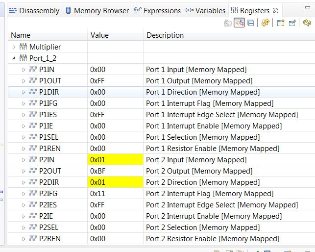
For example, the voltage of P2.0 (pin 20) remains at ~0V even when we set the P2 registers as follows:

P2REN = 0x00

P2SEL = 0x00

P2DIR = 0x01

P2OUT = 0x01

We confirmed that we can control other port 2 pins in this way. For example when we use similar settings on bit 3, we observe ~VDD at P2.3 (pin 23).

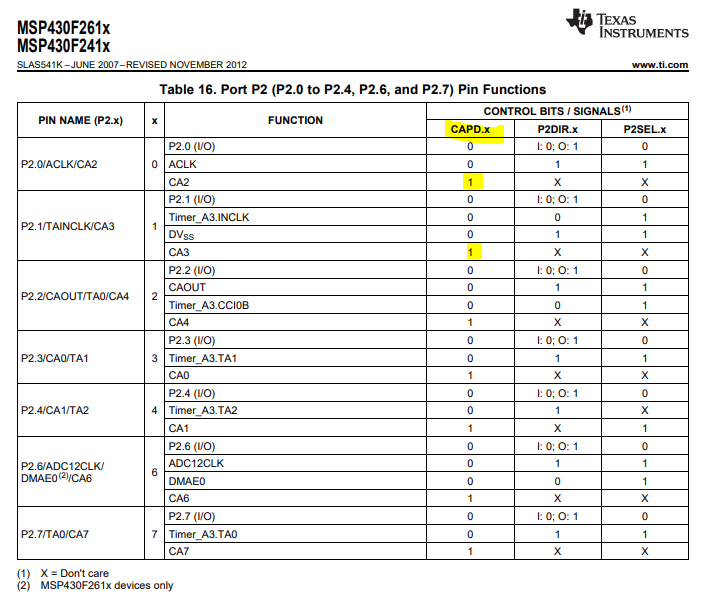
We have also confirmed that the CAPD register bits and the P2CAx register bits are all 0. 

Is there some other register besides the ones listed that control P2.0 and P2.1 gpio function? This is a mature device so I'm sure this has been answered before but I couldn't find anything on E2E.

Thanks

  • You don't show any actual code so I can't comment on that. If that matches your description then they should be outputs. Are the pins connected to something else that could be pulling them down?

    Try leaving the pins configured as inputs (PUC does that) and measure the voltage at the pin. Both without and with an external pullup resistor. If it stays at 0V with the pullup then the pin is shorted to ground somewhere.

  • David,

    I confirm that there is nothing externally connected to the P2.0 pin. The signal is not even routed on the PCB but I am probing directly on the pin. After a PUC, I probed the pin using a voltmeter with and without a pull-up to 3.3V and here are the results.

    • No external resistor, Voltage measured at the pin = 0V
    • 5.5Kohm pull-up to 3.3V, Voltage measured at pin = 3.3V

    I then run this code:

        P2DIR |= BIT0;                  // configure P2.0 as output
        P2OUT |= BIT0;                  // Set P2.0 high

    And repeat the measurements:

    • No external resistor, Voltage measured at the pin = 0V
    • 5.5Kohm pull-up to 3.3V, Voltage measured at pin = 3.3V
    • 5.5Kohm pull-down to 0V, Voltage measured at pin = 0V

    Similar experiments with P2.3 yield the expected results of the pin voltage reflecting the register programming.

    Thanks,

    Ruben

  • The next thing is a sanity check on the compiler. BIT0 might not mean what you think it does so examine the assembly code generated. I use "msp430-elf-objdump -S" from the gcc tools. You ought to see a "bis.b #1,&P2DIR"

  • Check. The BIT0 definition is correct and the compiler is generating the correct code. See below screenshot of the CCS register view after running the two lines of code.

  • Hey Ruben,

    I'm looking at the pin diagram for those GPIOs, and it looks like the comparator module has the ability to override the GPIO functionality with the CAPD.x bits.  Can you check these bits as well?  

    Thanks,

    JD

  • JD,

    Yes I checked the CAPD bits and there is even an errata associated with those. When I found that I was confident that those were the cause of my issue, but I've checked the comparator bits and they seem to all be set correctly per my understanding. See screenshot below. I still feel it must have something to do with this but I'm not sure what/how.

    Thanks!

  • Have you tried out the simplest possible program? (disable watch dog and set P2OUT and P2DIR)

    If you can't get an output in that case I would suspect a hardware failure.

  • Yes I have tried the simplest program as you suggest with no effect on those pins.  I also suspect a h/w issue but I find it strange that this affects multiple PCBs in exactly the same way and that the MSP is otherwise fully functional.

  • Ruben,

    This does seem a bit weird.  Hardware damage does seem most likely.    

    How many boards/devices are you seeing this on?  

    It wasn't clear to me, are you able to measure the voltage difference when you are setting the internal pull-up/pull-down?  

    Just for a sanity check, I can test toggling these GPIO here in the lab.  I don't have any MSP430F261x devices here, so I ordered some samples that should be here early next week.  

    Thanks,

    JD

  • Thanks JD! This is happening on 3 new DV8885 EVMs recently ordered through the TI store. They were minimally handled before we observed this issue. I also ordered samples of the F2617 and an 80pin ZIF board to test this. We're not blocked by this but now I'm really curious.

  • I found that the problem here was operator error. I was referencing the wrong pin diagram for the device. I apologize for the waste of time on this but thanks for the help.

**Attention** This is a public forum