This thread has been locked.

If you have a related question, please click the "Ask a related question" button in the top right corner. The newly created question will be automatically linked to this question.

MSP430FR5989-EP: Low power mode 3.5

Part Number: MSP430FR5989-EP
Other Parts Discussed in Thread: MSP430WARE, MSP430FR6989, RM48L952, ENERGYTRACE

Hello Everyone,

We have used TMS5703137CGWTMEP Microcontroller in our design. As the MCU doesn't have RTC & we have temperature limitation, we have also selected MSP430FR5989-EP  only for RTC purporse.

Can anybody please explain me how to use only RTC in LPM3.5 mode.

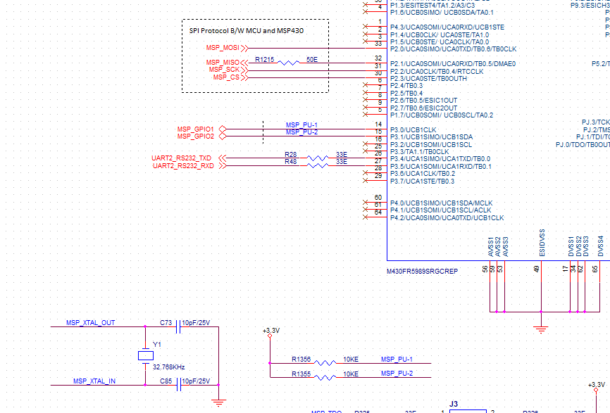
attached MSP430FR5989-EP ckt in our design for reference. as in image, pin no. 14 & 15 is connected to TMS5703137CGWTMEP MCU for LPM purpose.

  • Example msp430fr69xx_lpm3-5_01.c demonstrates using LPM3.5 with an RTC wakeup:

    https://dev.ti.com/tirex/explore/node?node=AFyv-fW9sxHfoEm94nud.Q__IOGqZri__LATEST

    Example msp430fr69xx_lpm4-5_01.c demonstrates using LPM4.5 with a pin wakeup:

    https://dev.ti.com/tirex/explore/node?node=AOgGKPNEcmInD2zOl9llyw__IOGqZri__LATEST

    You'll want to combine the two to get LPM3.5 with a pin wakeup. (You might want an RTC wakeup as well.) The only difference between LPM3.5 and LPM4.5 is whether the RTC is running.

    In both examples, the GPIOs are configured (en masse) for output-low, assuming that nothing is connected to any of the pins. You should audit these settings to make sure you don't set up bus conflicts with some of your external connections.

  • Hi Bruce,

    I have attached our code for your reference. Please check whether configuration to LPM3.5 is correct.

    Below is the code.

    /*
    --COPYRIGHT--,BSD_EX
    * Copyright (c) 2014, Texas Instruments Incorporated
    * All rights reserved.
    *
    * Redistribution and use in source and binary forms, with or without
    * modification, are permitted provided that the following conditions
    * are met:
    *
    * * Redistributions of source code must retain the above copyright
    * notice, this list of conditions and the following disclaimer.
    *
    * * Redistributions in binary form must reproduce the above copyright
    * notice, this list of conditions and the following disclaimer in the
    * documentation and/or other materials provided with the distribution.
    *
    * * Neither the name of Texas Instruments Incorporated nor the names of
    * its contributors may be used to endorse or promote products derived
    * from this software without specific prior written permission.
    *
    * THIS SOFTWARE IS PROVIDED BY THE COPYRIGHT HOLDERS AND CONTRIBUTORS "AS IS"
    * AND ANY EXPRESS OR IMPLIED WARRANTIES, INCLUDING, BUT NOT LIMITED TO,
    * THE IMPLIED WARRANTIES OF MERCHANTABILITY AND FITNESS FOR A PARTICULAR
    * PURPOSE ARE DISCLAIMED. IN NO EVENT SHALL THE COPYRIGHT OWNER OR
    * CONTRIBUTORS BE LIABLE FOR ANY DIRECT, INDIRECT, INCIDENTAL, SPECIAL,
    * EXEMPLARY, OR CONSEQUENTIAL DAMAGES (INCLUDING, BUT NOT LIMITED TO,
    * PROCUREMENT OF SUBSTITUTE GOODS OR SERVICES; LOSS OF USE, DATA, OR PROFITS;
    * OR BUSINESS INTERRUPTION) HOWEVER CAUSED AND ON ANY THEORY OF LIABILITY,
    * WHETHER IN CONTRACT, STRICT LIABILITY, OR TORT (INCLUDING NEGLIGENCE OR
    * OTHERWISE) ARISING IN ANY WAY OUT OF THE USE OF THIS SOFTWARE,
    * EVEN IF ADVISED OF THE POSSIBILITY OF SUCH DAMAGE.
    *
    *******************************************************************************
    *
    * MSP430 CODE EXAMPLE DISCLAIMER
    *
    * MSP430 code examples are self-contained low-level programs that typically
    * demonstrate a single peripheral function or device feature in a highly
    * concise manner. For this the code may rely on the device's power-on default
    * register values and settings such as the clock configuration and care must
    * be taken when combining code from several examples to avoid potential side
    * effects. Also see www.ti.com/grace for a GUI- and www.ti.com/msp430ware
    * for an API functional library-approach to peripheral configuration.
    *
    * --/COPYRIGHT--
    ******************************************************************************
    // MSP430F59xx Demo - eUSCI_A0, SPI 4-Wire Slave Data Echo
    //
    // Description: SPI slave talks to SPI master using 4-wire mode. Data received
    // from master is echoed back.
    // ACLK = 32.768kHz, MCLK = SMCLK = DCO ~ 1MHz
    // Note: Ensure slave is powered up before master to prevent delays due to
    // slave init.
    //
    //
    // MSP430FR6989
    // -----------------
    // /|\ | XIN|-
    // | | | 32KHz Crystal
    // ---|RST XOUT|-
    // | |
    // | P2.0|-> Data Out (UCA0SOMI)
    // | |
    // | P2.1|<- Data In (UCA0SIMO)
    // | |
    // | P1.5|-> Serial Clock Out (UCA0CLK)
    // | P1.4|<- Slave Select (UCA0STE)
    //
    //
    // William Goh
    // Texas Instruments Inc.
    // April 2014
    // Built with IAR Embedded Workbench V5.60 & Code Composer Studio V6.0
    ****************************************************************************/

    /*
    * Clock sources default Configuration after reset
    * ==========================================================================================================
    * 1) SMCLK : Subsystem master clock is ON
    * 2) VLO : Internal very-low-power low-frequency oscillator is OFF
    * 3) LFXTCLK : Low-frequency oscillator is OFF
    * 3.1) LFXT bypass : LFXT sourced from external crystal (RESET)
    * 3.2) LFXTDRIVE : Maximum drive strength and maximum current consumption LFXT oscillator(3h)
    * 4) HFXTCLK : High-frequency oscillator is OFF
    * 5) DCOCLK : Internal digitally controlled oscillator (DCO) is ON (DCO clock is by default 4 MHz).
    * 6) MODCLK : Internal low-power oscillator with 5-MHz typical frequency
    * ===========================================================================================================
    */


    #include "main.h"
    #include "Peripheral_Init.h"
    #include "MSP430_Flash.h"
    #include "SRAM.h"


    //#define DEBUGPORT_UART

    #if defined(__TI_COMPILER_VERSION__)
    #pragma DATA_SECTION(FRAM_writeRead,".infoA")
    uint16_t FRAM_writeRead[WRITE_SIZE]={0};
    #elif defined(__IAR_SYSTEMS_ICC__)
    __persistent unsigned long FRAM_write[WRITE_SIZE] = {0};
    #elif defined(__GNUC__)
    unsigned long __attribute__((persistent)) FRAM_write[WRITE_SIZE] = {0};
    #else
    #error Compiler not supported!
    #endif

    volatile uint8_t Rxdata=0;
    RTC_t Calender_Time;

    uint8_t RTCUpdateFlag=0;
    void SendRTCData(void);
    volatile uint8_t UartRXData = 0;
    volatile uint8_t UartTXData = 1;

    volatile uint8_t RTC_Counter=0;


    int main(void)
    {

    uint16_t Delay=0;
    // Stop WatchDog Timer
    WDTCTL = WDTPW | WDTHOLD;

    for(Delay=0;Delay<1000;Delay++);
    //Configure PinMux
    PinMux();

    // Disable the GPIO power-on default high-impedance mode to activate
    // previously configured port settings
    PM5CTL0 &= ~LOCKLPM5;

    // Configure the System Clock
    SystemClockConfig();

    //Configure the RTC parameter
    Calender_Time.Sec = 30;
    Calender_Time.Min = 43;
    Calender_Time.Hour = 18;
    Calender_Time.Day_of_week =3;
    Calender_Time.Day = 24;
    Calender_Time.Month = 9;
    Calender_Time.Year = 2020;

    //Initilaize the MSP430 Peripherals
    MSP430_PeripheralInit();

    // SET the P4.0 to Default High state,
    // Once P4.0 is Low ,generate interrupt to master to start fetching RTC value
    // P4.0 low to high transaction will happen inside RTC ISR
    P3OUT = 0x01;


    // By default, RTC_UpdateCmplt will be cleared
    Calender_Time.RTC_UpdateCmplt=RESET;

    //Flash Test Program it Gets the software checksum and Version, it compute the checksum
    FlashTestProgram();

    //Enter LPM3 mode w/ interrupts enabled
    __bis_SR_register(LPM4_bits| GIE);
    //__bis_SR_register( LPM3_bits | GIE);
    while(1)
    {
    if(Calender_Time.RTC_UpdateCmplt==SET)
    {
    // Re-init with New RTC value
    RTC_Initialisation(&Calender_Time);

    // Reset the RTC update completion flag after update.
    Calender_Time.RTC_UpdateCmplt=RESET;

    // Enter LPM3 mode w/ interrupts enabled
    __bis_SR_register(LPM4_bits| GIE);
    }
    }

    #ifdef DEBUGPORT_UART
    while(1)
    {
    while(!(UCA1IFG & UCTXIFG));
    UCA1TXBUF = UartTXData; // Load data onto buffer
    /*while(!(UCA1IFG & UCRXIFG));
    UartRXData = UCA1RXBUF; // Load data onto buffer
    UartTXData++;*/

    //__bis_SR_register(LPM3_bits| GIE); // Enter LPM3 mode w/ interrupts enabled
    __bis_SR_register(LPM4_bits| GIE);
    }
    #endif
    }


    /*------------------------------------------------------------------------------------------------
    FUNCTION NAME: SendRTCValuetoMaster()
    DESCRIPTION : Send the Update RTC value to Master Board
    PARAMETERS : command is of type uint8_t
    RETURN : None
    --------------------------------------------------------------------------------------------------*/
    inline void SendRTCValuetoMaster(uint8_t u8Command)
    {
    switch(u8Command)
    {
    case Dummy_Write:
    Rxdata=Calender_Time.Sec;
    UCA0TXBUF=Rxdata;// In RTC_ISR Txbuf is loaded with RTCSEC;Load next byte as min
    break;
    case CMD_SEC:
    Rxdata=Calender_Time.Min;
    UCA0TXBUF=Rxdata;// In RTC_ISR Txbuf is loaded with RTCSEC;Load next byte as min
    break;
    case CMD_MIN:
    Rxdata= Calender_Time.Hour;
    UCA0TXBUF=Rxdata; // Tx would have went Min;Load next byte as hour
    break;
    case CMD_HOUR:
    Rxdata=Calender_Time.Day_of_week ;
    UCA0TXBUF=Rxdata; // Tx would have went hour;Load next byte as Day of week
    break;
    case CMD_DOW:
    Rxdata= Calender_Time.Day;
    UCA0TXBUF=Rxdata; // Tx would have went Day of week;Load next byte as day
    break;
    case CMD_DAY:
    Rxdata= Calender_Time.Month ;
    UCA0TXBUF=Rxdata;// Tx would have went Day ;Load next byte as month
    break;
    case CMD_MONTH:
    Rxdata= (uint8_t) (Calender_Time.Year & 0xff) ;
    UCA0TXBUF=Rxdata;// Tx would have went month;Load next byte as year lsb
    break;
    case CMD_YEAR_LSB:
    Rxdata= ((Calender_Time.Year>>8) & 0xff);
    UCA0TXBUF=Rxdata;
    break;
    case CMD_YEAR_MSB:
    // Set the P4.0 to Low
    P3OUT = 0x01;
    //Dummy Transmit from master side to Receive the MSB value of Year to Master side
    // Tx would have went year lsb;Load next byte as year msb
    break;
    default:
    break;
    }
    }


    /*------------------------------------------------------------------------------------------------
    FUNCTION NAME: GetRTCValuefromMaster()
    DESCRIPTION : Get the New RTC value from Master Board
    PARAMETERS : command is of type uint8_t, new RTC data is of type uint8_t
    RETURN : None
    --------------------------------------------------------------------------------------------------*/
    inline void GetRTCValuefromMaster(uint8_t u8Command,uint8_t u8NewRTCData)
    {
    switch(u8Command)
    {
    case CMD_SEC:
    Calender_Time.Sec=u8NewRTCData;
    UCA0TXBUF=0xA2; // Tx would have went 0xA1;Load next byte as 0xA2
    Calender_Time.RTC_UpdateCounter=2;
    break;
    case CMD_MIN:
    Calender_Time.Min=u8NewRTCData;
    UCA0TXBUF=0xA3; // Tx would have went 0xA2;Load next byte as 0xA3
    Calender_Time.RTC_UpdateCounter=3;
    break;
    case CMD_HOUR:
    Calender_Time.Hour=u8NewRTCData;
    UCA0TXBUF=0xA4; // Tx would have went 0xA3;Load next byte as 0xA4
    Calender_Time.RTC_UpdateCounter=4;
    break;
    case CMD_DOW:
    Calender_Time.Day_of_week=u8NewRTCData;
    UCA0TXBUF=0xA5; // Tx would have went 0xA4;Load next byte as 0xA5
    Calender_Time.RTC_UpdateCounter=5;
    break;
    case CMD_DAY:
    Calender_Time.Day=u8NewRTCData;
    UCA0TXBUF=0xA6; // Tx would have went 0xA5;Load next byte as 0xA6
    Calender_Time.RTC_UpdateCounter=6;
    break;
    case CMD_MONTH:
    Calender_Time.Month=u8NewRTCData;
    UCA0TXBUF=0xA7; // Tx would have went 0xA6;Load next byte as 0xA7
    Calender_Time.RTC_UpdateCounter=7;
    break;
    case CMD_YEAR_LSB:
    Calender_Time.Year=(uint8_t)u8NewRTCData;
    UCA0TXBUF=0xA8; // Tx would have went 0xA7;Load next byte as 0xA8
    Calender_Time.RTC_UpdateCounter=8;
    break;
    case CMD_YEAR_MSB: //Dummy Transmit from master side to Receive the MSB value of Year to Master side
    Calender_Time.Year|=(uint16_t)(u8NewRTCData<<8);
    UCA0TXBUF=0; // Tx would have went 0xA8;Load next byte as 0x00
    Calender_Time.RTC_UpdateCounter=RESET;
    Calender_Time.RTC_UpdateNewFlag=RESET;
    Calender_Time.RTC_UpdateCmplt=SET;
    break;
    }
    }

    void PinMux(void)
    {
    // Configure GPIO
    //P1SEL0 |= BIT5 | BIT4 | BIT6 | BIT7; //Pin-Mux is configured for UCB0.
    //P1SEL1 |= BIT5 | BIT4; // Configure P1.4-->slave select and
    P2SEL0 |= BIT0 | BIT1 | BIT2 | BIT3; // Configure P2.0-->MOSI and P2.1-->MISO and P2.2-->clk and P2.3-->slave select
    P3SEL0 |= BIT4 | BIT5; // Configure UART for P3.4-->USCATXD and P3.5-->USCARXD
    PJSEL0 |= BIT4 | BIT5; // For XT1
    }


    /*------------------------------------------------------------------------------------------------
    FUNCTION NAME: SystemClockConfig()
    DESCRIPTION : Configuration the System clock
    PARAMETERS : void
    RETURN : None
    --------------------------------------------------------------------------------------------------*/
    void SystemClockConfig(void)
    {
    // Configure the System Clock from DCOCLK to 1 MHz
    // ACLK-> LFXTCLK(Low-frequency oscillator) - 32,768Hz , MCLK-> DCOCLK(Internal digitally controlled oscillator)
    // SMCLK-> DCOCLK.
    // XT1 Setup
    CSCTL0_H = CSKEY >> 8; // Unlock CS(Clock System) registers
    CSCTL1 = DCOFSEL_0; // Set DCO to 1MHz
    CSCTL1 &= ~DCORSEL; // For low-speed devices configuration of DCO, it is always to 0. for only DCO keeping at 1MHz
    CSCTL2 = SELA__LFXTCLK | SELS__DCOCLK | SELM__DCOCLK; // ACLK-> LFXTCLK(Low-frequency oscillator) - 32,768HZ , MCLK-> DCOCLK(Internal digitally controlled oscillator)
    // SMCLK-> DCOCLK.
    CSCTL3 = DIVA__1 | DIVS__1 | DIVM__1; // Set all dividers
    CSCTL4 &= ~LFXTOFF; // LFXT (Low-frequency oscillator) is on
    do
    {
    CSCTL5 &= ~LFXTOFFG; // Clear XT1 fault flag , No fault condition occurred after the last reset
    SFRIFG1 &= ~OFIFG; // Oscillator fault interrupt flag clear for No interrupt pending
    }while (SFRIFG1&OFIFG); // Test oscillator fault flag
    CSCTL0_H = 0; // Lock CS (Clock System) registers
    }

    /*------------------------------------------------------------------------------------------------
    FUNCTION NAME: SPIInitConfig()
    DESCRIPTION : Initailize the SPI Peripheral
    PARAMETERS : void
    RETURN : None
    --------------------------------------------------------------------------------------------------*/
    void SPIInitConfig(void)
    {
    // Configure USCI_A0 for SPI Slave Operation
    UCA0CTLW0 = UCSWRST; // Put state machine in reset**
    UCA0CTLW0 |= UCSYNC| UCMSB | UCMODE_2 | UCSTEM|UCCKPL|UCCKPH; // 4-pin, 8-bit SPI slave, Clock polarity Low, MSB First , 8- BIT configuration
    UCA0CTLW0 |= UCSSEL__UCLK; // UCLK for SPI Slave, because master Board will generate clock for slave
    UCA0BR0 = 0x02; // Configure Bit Rate Control Register to 2
    UCA0BR1 = 0;
    //UCB0MCTLW = 0; // No modulation
    UCA0CTLW0 &= ~UCSWRST; // Initialize USCI state machine
    UCA0IE |= UCRXIE; // Enable USCI_A0 SPI RX interrupt
    }


    /*------------------------------------------------------------------------------------------------
    FUNCTION NAME: GpioInitConfig()
    DESCRIPTION : Configure GPIO Pin
    PARAMETERS : void
    RETURN : None
    --------------------------------------------------------------------------------------------------*/
    void GpioInitConfig(void)
    {
    //P1DIR|=BIT0; // Configure the Port 1.0 as Output which is connected to LED1
    P3DIR|=BIT0 | BIT1; // Configure the Port 3.0 as Output which is connected to RM48L952 to generate interrupt
    }

    /*------------------------------------------------------------------------------------------------
    FUNCTION NAME: UARTInitConfig()
    DESCRIPTION : Initialize the UART peripheral
    PARAMETERS : void
    RETURN : None
    --------------------------------------------------------------------------------------------------*/
    void UARTInitConfig(void)
    {

    // Configure USCI_A0 for UART mode
    UCA1CTL1 |= UCSWRST;
    UCA1CTL1 = UCSSEL__ACLK; // Set ACLK = 32768 as UCBRCLK
    UCA1BR0 = 3; // 9600 baud
    UCA1MCTLW = 0x5300; // 32768/9600 - INT(32768/9600)=0.41
    // UCBRSx value = 0x53 (See UG)
    UCA1BR1 = 0;
    // UCA1STATW |=(1<<7);
    UCA1CTL1 &= ~UCSWRST; // Release from reset
    UCA1IE |= UCRXIE; // Enable USCI_A0 RX interrupt

    }

    /*------------------------------------------------------------------------------------------------
    FUNCTION NAME: MSP430_PeripheralInit()
    DESCRIPTION : Initialize the MSP430 peripheral
    PARAMETERS : void
    RETURN : None
    --------------------------------------------------------------------------------------------------*/
    void MSP430_PeripheralInit(void)
    {
    //Initialization of GPIO Pins
    GpioInitConfig();

    //Initialization of SPI peripheral
    SPIInitConfig();

    #ifdef DEBUGPORT_UART
    //Initialization of UART peripheral
    UARTInitConfig();
    #endif

    //Initialise the RTC peripheral.
    RTC_Initialisation(&Calender_Time);
    }

    /*------------------------------------------------------------------------------------------------
    FUNCTION NAME: RTC_Initialisation()
    DESCRIPTION : Initialize the RTC peripheral
    PARAMETERS : void
    RETURN : None
    --------------------------------------------------------------------------------------------------*/
    void RTC_Initialisation(RTC_t *RtcCalender)
    {
    // Real-time clock key. This register should be written with A5h to unlock RTC_C. A
    // write with a value other than A5h locks the module. A read from this register
    // always returns 96h.
    RTCCTL0_H=RTC_UNLOCK;

    // Calendar mode and Minute changed
    RTCCTL1 = RTCMODE + RTCTEV_0;

    // The calendar is stopped as well as the Pre-scaler counters, RT0PS and RT1PS
    RTCCTL1 |= RTCHOLD;

    //Update the RTC parameter to the RTC register
    RTCSEC = RtcCalender->Sec;
    RTCMIN = RtcCalender->Min;
    RTCHOUR = RtcCalender->Hour;
    RTCDOW = RtcCalender->Day_of_week;
    RTCDAY = RtcCalender->Day;
    RTCMON = RtcCalender->Month;
    RTCYEAR = RtcCalender->Year;

    // Enable RTC read ready and RTC time event interrupt
    RTCCTL0_L = RTCTEVIE | RTCRDYIE;

    //Real-time clock (calendar mode) is operational.(Release the RTC)
    RTCCTL1 &= ~RTCHOLD;
    }

  • This is a fair amount of code, and I'm at my "day job", so I won't be able to look at this before this evening.

    In the meantime: What does it do when you run it?

  • Is your goal LPM4 or LPM3.5? This code uses LPM4.

    For LPM4 it appears OK. Your UART won't run in LPM4, but I don't see any uses of it. I don't see any ISRs, but the SPI is capable of waking you from LPM4.

    For LPM3.5, there's some code missing. Also, I don't see how the host will contact the MSP430 while in LPM3.5, since the SPI is inoperative. I imagined MSP_PU-1/2 (P3.0/1) would be used as wakeup pins, but they seem to be pointed out, towards the host.

    Entry to LPM3.5 is described in User Guide (SLAU367P) Sec 1.4.3.1,but the distinctive items are:

    1) The LDO is turned off on entry to LPMx.5:

    PMMCTL0_H = PMMPW_H; // Open PMM Registers for write
    PMMCTL0_L |= PMMREGOFF; // and set PMMREGOFF


    2) Wakeup happens via a Reset (restart) up at main(). It doesn't restart from the LPM entry

    Since the SPI won't wake you from LPM3.5, and you have no wakeup pins, maybe LPM4 is what you really want.

  • Hi Bruce,

    My goal is to operate in LPM3.5.

    With the code I have shared earlier, MSP430 IC is drawing approximately 200uA of current. So I think it is operating in active mode.

    How can I confirm whether it is operating in active or low power mode? also how to change this from active mode?

  • 200uA is quite a lot for LPM4. Things to check for:

    1) All of your unused pins should be configured per User Guide (SLAU367P) Table 1-4. (When I do this, I make a checklist.) This avoids "chattering" in the Schmitt trigger which consumes power. This (probably) won't generate 200uA, but it could generate 50uA. Those Examples I mentioned do this, though as I mentioned before you should be prudent about it.

    2) Avoid bus conflicts; these can consume considerable current. Are P3.0/1 connected to the RM48 now? If so, how are the pins at that end configured? If it is driving them also, that's a bus conflict.

    3) What wakeup (from LPM4) sources are you using? This code doesn't have any ISRs in it, so it's hard for me to tell. If you're waking up too often you'll lose much of the benefit of LPM.

    Even if your long-term goal is LPM3.5, I suggest you first get LPM4 down to e.g. <5uA, since LPM4 is easier to work with.

  • thank you for earlier replay

    1)1. In LPM 3.5 with RTC IS not running when checked on energy trace technology,

    For below code:
     
    PMMCTL0_H = PMMPW_H;                      // Open PMM Registers for write
    PMMCTL0_L |= PMMREGOFF;                   // and set PMMREGOFF
     
    // Enter LPM4 mode w/ interrupts enabled
    __bis_SR_register(LPM4_bits| GIE);
     
    And taking current of 56uA.
     
    Can SPI INTERRUPT will work on LPM3.5, to read RTC values from master controller, why RTC is not running in LPM3.5?
     
    and in LPM3.5 RTC IS not running.
     
     
    2) RTC clock is working in LPM4 with 0.80uA without connecting Debugger tool               
       when checked in multi meter.When checked with Debugger it is taking around 106uA current.
    3) In LPM4 SPI receiver with SPI Receiver interrupt FLAG is enabled to red RTC data, when connect to debugger it is taking 130.11uA current, in this LPM4 RTC is working fine, without debugger .90uA current is taking.
     
    why interrupt not generating in LPM3.5 and also RTC not working but it is going to LPM3.5?
     
    1. In LPM 3.5 with RTC IS not running when checked on energy trace technology,
    For below code:
     
    PMMCTL0_H = PMMPW_H;                      // Open PMM Registers for write
    PMMCTL0_L |= PMMREGOFF;                   // and set PMMREGOFF
     
    // Enter LPM4 mode w/ interrupts enabled
    __bis_SR_register(LPM4_bits| GIE);
     
    And taking current of 56uA.
     
    Can SPI INTERRUPT will work on LPM3.5, to read RTC values from master controller, why RTC is not running in LPM3.5?


    2. RTC clock is working in LPM4 with 0.80uA without connecting Debugger tool                when checked in multi meter.
     
    When checked with Debugger it is taking around 106uA current.
    3. In LPM4 SPI receiver with SPI Receiver interrupt FLAG is enabled to red RTC data, when connect to debugger it is taking 130.11uA current, in this LPM4 RTC is working fine, without debugger .90uA current is taking.


  • 1) The SPI will not wake the CPU from LPM3.5. [Ref User Guide (SLAU367P) Sec 1.4] An RTC interrupt will not serve your communication purposes, so you will need a pin interrupt to provide a wakeup.

    2) How do you tell that the RTC isn't running? I'm not sure EnergyTrace++ can tell whether the RTC is running in LPM3.5.

    3) Are you using Free Run or (standard) Run? Free Run is recommended for EnergyTrace measurements, since (standard) Run will give false readings.

    4) The code you posted has multiple LPM(4) points. Which one(s) did you change for LPM3.5?

    5) The startup (main) code you posted has no provision for LPM3.5. What code have you added there?

    I (still) suggest you work with LPM4 until you consistently get the results you want. LPM3.5 will add a number of new variables.

**Attention** This is a public forum