


Other Parts Discussed in Thread: TM4C1294NCZAD
Tool/software: Code Composer Studio
Hey Bob, I was working on a project involving sampling external analog signal. I saw your post above in which you provided with a example file. So, I tried to run the code with small modification as I am working on DK-TM4C129X. My project files are attached below.
#include <stdbool.h>
#include <stdint.h>

#include "inc/hw_ints.h"
#include "inc/hw_memmap.h"
#include "inc/hw_adc.h"
#include "inc/hw_types.h"
#include "inc/hw_udma.h"
#include "driverlib/debug.h"
#include "driverlib/gpio.h"
#include "driverlib/interrupt.h"
#include "driverlib/pin_map.h"
#include "driverlib/sysctl.h"
#include "driverlib/uart.h"
#include "driverlib/adc.h"
#include "driverlib/udma.h"
#include "driverlib/timer.h"
#include "driverlib/rom.h"
#include "driverlib/rom_map.h"
#include "driverlib/systick.h"
#include "utils/uartstdio.h"

#define ADC_SAMPLE_BUF_SIZE     64

enum BUFFERSTATUS
                  { EMPTY,
                    FILLING,
                    FULL
                  };

#pragma DATA_ALIGN(ucControlTable, 1024)
uint8_t ucControlTable[1024];

static uint16_t ADC_Out1[ADC_SAMPLE_BUF_SIZE];
static uint16_t ADC_Out2[ADC_SAMPLE_BUF_SIZE];
static enum BUFFERSTATUS BufferStatus[2];

void ConfigureUART(void);
void init_ADC(void);
void init_TIMER(void);
void init_DMA(void);
static uint32_t g_ui32DMAErrCount = 0u;
static uint32_t g_ui32SysTickCount;


void uDMAErrorHandler(void)
{
    uint32_t ui32Status;
    ui32Status = MAP_uDMAErrorStatusGet();
    if(ui32Status)
    {
        MAP_uDMAErrorStatusClear();
        g_ui32DMAErrCount++;
    }
}

// Not used in this example, but used to debug to make sure timer interrupts happen
void Timer0AIntHandler(void)
{
    //
    // Clear the timer interrupt flag.
    //
    TimerIntClear(TIMER0_BASE, TIMER_TIMA_TIMEOUT);
}

void SysTickIntHandler(void)
{
    // Update our system tick counter.
    g_ui32SysTickCount++;
}

void ADCseq0Handler()
{
    ADCIntClear(ADC0_BASE, 0);

    if ((uDMAChannelModeGet(UDMA_CHANNEL_ADC0 | UDMA_PRI_SELECT) == UDMA_MODE_STOP)
            && (BufferStatus[0] == FILLING))
    {
        BufferStatus[0] = FULL;
        BufferStatus[1] = FILLING;
    }
    else if ((uDMAChannelModeGet(UDMA_CHANNEL_ADC0 | UDMA_ALT_SELECT) == UDMA_MODE_STOP)
            && (BufferStatus[1] == FILLING))

    {
        BufferStatus[0] = FILLING;
        BufferStatus[1] = FULL;
    }
}

int main(void)
{
    uint32_t i, average1, average2, samples_taken;
    // Set the system clock to run at 80MHz from the PLL.
    //SysCtlClockSet(SYSCTL_SYSDIV_2_5|SYSCTL_USE_PLL|SYSCTL_OSC_MAIN|SYSCTL_XTAL_16MHZ);
    SysCtlClockFreqSet((SYSCTL_XTAL_25MHZ |
                            SYSCTL_OSC_MAIN |
                               SYSCTL_USE_PLL |
                              SYSCTL_CFG_VCO_480), 120000000);

    SysCtlDelay(20u);

    MAP_SysCtlPeripheralEnable(SYSCTL_PERIPH_TIMER0);  //Enable the clock to TIMER0
    MAP_SysCtlPeripheralEnable(SYSCTL_PERIPH_ADC0);    //Enable the clock to ADC module
    MAP_SysCtlPeripheralEnable(SYSCTL_PERIPH_UDMA);    //Enable the clock to uDMA
    MAP_SysCtlPeripheralEnable(SYSCTL_PERIPH_GPIOE);   //Enables the clock to PORT E
    MAP_SysCtlDelay(30u);

    MAP_SysTickPeriodSet(SysCtlClockGet() / 100000u); //Sets the period of the SysTic counter to 10us
    MAP_SysTickIntEnable();
    MAP_SysTickEnable();

    BufferStatus[0] = FILLING;
    BufferStatus[1] = EMPTY;
    samples_taken = 0u;

    ConfigureUART();
    UARTprintf("Timer->ADC->uDMA demo!\n");
    UARTprintf("\tAverage1\tAverage2\tTotal Samples\n");

    init_DMA();
    init_ADC();
    init_TIMER();

    MAP_IntMasterEnable();
    MAP_TimerEnable(TIMER0_BASE, TIMER_A); // Start everything


    while(1)
    {
        if(BufferStatus[0u] == FULL)
        {
            // Do something with data in ADC_OUT1
            average1 = 0u;
            for(i =0u; i < ADC_SAMPLE_BUF_SIZE; i++)
            {
                average1 += ADC_Out1[i];
                ADC_Out1[i] = 0u;
            }
            BufferStatus[0u] = EMPTY;
            // Enable for another uDMA block transfer
            uDMAChannelTransferSet(UDMA_CHANNEL_ADC0 | UDMA_PRI_SELECT, UDMA_MODE_PINGPONG, (void *)(ADC0_BASE + ADC_O_SSFIFO0), &ADC_Out1, ADC_SAMPLE_BUF_SIZE);
            uDMAChannelEnable(UDMA_CHANNEL_ADC0 | UDMA_PRI_SELECT); // Enables DMA channel so it can perform transfers
            samples_taken += ADC_SAMPLE_BUF_SIZE;
            average1 = (average1 + (ADC_SAMPLE_BUF_SIZE / 2u)) / ADC_SAMPLE_BUF_SIZE;
        }
        if(BufferStatus[1u] == FULL)
        {
            // Do something with data in ADC_OUT2
            average2 = 0u;
            for(i =0u; i < ADC_SAMPLE_BUF_SIZE; i++)
            {
                average2 += ADC_Out2[i];
                ADC_Out2[i] = 0u;
            }
            BufferStatus[1u] = EMPTY;
            // Enable for another uDMA block transfer
            uDMAChannelTransferSet(UDMA_CHANNEL_ADC0 | UDMA_ALT_SELECT, UDMA_MODE_PINGPONG, (void *)(ADC0_BASE + ADC_O_SSFIFO0), &ADC_Out2, ADC_SAMPLE_BUF_SIZE);
            uDMAChannelEnable(UDMA_CHANNEL_ADC0 | UDMA_ALT_SELECT);
            samples_taken += ADC_SAMPLE_BUF_SIZE;
            average2 = (average2 + (ADC_SAMPLE_BUF_SIZE / 2u)) / ADC_SAMPLE_BUF_SIZE;
            UARTprintf("\t%d\t\t%d\t\t%d\r", average1,average2,samples_taken);
        }
    }
}


void init_TIMER()
{
    MAP_TimerConfigure(TIMER0_BASE, TIMER_CFG_SPLIT_PAIR | TIMER_CFG_A_PERIODIC);
    // Set sample frequency to 16KHz (every 62.5uS)
    MAP_TimerLoadSet(TIMER0_BASE, TIMER_A, MAP_SysCtlClockGet()/16000 -1);   //TODO: Timer Load Value is set here
    MAP_TimerControlTrigger(TIMER0_BASE, TIMER_A, true);
    MAP_TimerControlStall(TIMER0_BASE, TIMER_A, true); //Assist in debug by stalling timer at breakpoints
}

void init_ADC()
{
    GPIOPinTypeADC(GPIO_PORTE_BASE, GPIO_PIN_2);
    SysCtlDelay(80u);

    // Use ADC0 sequence 0 to sample channel 0 once for each timer period
    ADCClockConfigSet(ADC0_BASE, ADC_CLOCK_SRC_PIOSC | ADC_CLOCK_RATE_HALF, 1);

    SysCtlDelay(10); // Time for the clock configuration to set

    IntDisable(INT_ADC0SS0);
    ADCIntDisable(ADC0_BASE, 0u);
    ADCSequenceDisable(ADC0_BASE,0u);
    // With sequence disabled, it is now safe to load the new configuration parameters

    ADCSequenceConfigure(ADC0_BASE, 0u, ADC_TRIGGER_TIMER, 0u);
    ADCSequenceStepConfigure(ADC0_BASE,0u,0u,ADC_CTL_CH0| ADC_CTL_END | ADC_CTL_IE);
    ADCSequenceEnable(ADC0_BASE,0u); //Once configuration is set, re-enable the sequencer
    ADCIntClear(ADC0_BASE,0u);
    ADCSequenceDMAEnable(ADC0_BASE,0);
    IntEnable(INT_ADC0SS0);

}

void init_DMA()
{
    uDMAEnable(); // Enables uDMA
    uDMAControlBaseSet(ucControlTable);

    uDMAChannelAttributeDisable(UDMA_CHANNEL_ADC0, UDMA_ATTR_ALTSELECT | UDMA_ATTR_HIGH_PRIORITY | UDMA_ATTR_REQMASK);

    uDMAChannelAttributeEnable(UDMA_CHANNEL_ADC0, UDMA_ATTR_USEBURST);
    // Only allow burst transfers

    uDMAChannelControlSet(UDMA_CHANNEL_ADC0 | UDMA_PRI_SELECT, UDMA_SIZE_16 | UDMA_SRC_INC_NONE | UDMA_DST_INC_16 | UDMA_ARB_1);
    uDMAChannelControlSet(UDMA_CHANNEL_ADC0 | UDMA_ALT_SELECT, UDMA_SIZE_16 | UDMA_SRC_INC_NONE | UDMA_DST_INC_16 | UDMA_ARB_1);

    uDMAChannelTransferSet(UDMA_CHANNEL_ADC0 | UDMA_PRI_SELECT, UDMA_MODE_PINGPONG, (void *)(ADC0_BASE + ADC_O_SSFIFO0), &ADC_Out1, ADC_SAMPLE_BUF_SIZE);
    uDMAChannelTransferSet(UDMA_CHANNEL_ADC0 | UDMA_ALT_SELECT, UDMA_MODE_PINGPONG, (void *)(ADC0_BASE + ADC_O_SSFIFO0), &ADC_Out2, ADC_SAMPLE_BUF_SIZE);

    uDMAChannelEnable(UDMA_CHANNEL_ADC0); // Enables DMA channel so it can perform transfers

}

//*****************************************************************************
//
// Configure the UART and its pins.  This must be called before UARTprintf().
//
//*****************************************************************************
void
ConfigureUART(void)
{
    //
    // Enable the GPIO Peripheral used by the UART.
    //
    MAP_SysCtlPeripheralEnable(SYSCTL_PERIPH_GPIOA);

    //
    // Enable UART0
    //
    MAP_SysCtlPeripheralEnable(SYSCTL_PERIPH_UART0);

    //
    // Configure GPIO Pins for UART mode.
    //
    MAP_GPIOPinConfigure(GPIO_PA0_U0RX);
    MAP_GPIOPinConfigure(GPIO_PA1_U0TX);
    MAP_GPIOPinTypeUART(GPIO_PORTA_BASE, GPIO_PIN_0 | GPIO_PIN_1);

    //
    // Use the internal 16MHz oscillator as the UART clock source.
    //
    UARTClockSourceSet(UART0_BASE, UART_CLOCK_PIOSC);

    //
    // Initialize the UART for console I/O.
    //
    UARTStdioConfig(0, 115200, 16000000);
}
//*****************************************************************************
//
// Startup code for use with TI's Code Composer Studio.
//
// Copyright (c) 2011-2014 Texas Instruments Incorporated.  All rights reserved.
// Software License Agreement
//
// Software License Agreement
//
// Texas Instruments (TI) is supplying this software for use solely and
// exclusively on TI's microcontroller products. The software is owned by
// TI and/or its suppliers, and is protected under applicable copyright
// laws. You may not combine this software with "viral" open-source
// software in order to form a larger program.
//
// THIS SOFTWARE IS PROVIDED "AS IS" AND WITH ALL FAULTS.
// NO WARRANTIES, WHETHER EXPRESS, IMPLIED OR STATUTORY, INCLUDING, BUT
// NOT LIMITED TO, IMPLIED WARRANTIES OF MERCHANTABILITY AND FITNESS FOR
// A PARTICULAR PURPOSE APPLY TO THIS SOFTWARE. TI SHALL NOT, UNDER ANY
// CIRCUMSTANCES, BE LIABLE FOR SPECIAL, INCIDENTAL, OR CONSEQUENTIAL
// DAMAGES, FOR ANY REASON WHATSOEVER.
//
//*****************************************************************************

#include <stdint.h>

//*****************************************************************************
//
// Forward declaration of the default fault handlers.
//
//*****************************************************************************
void ResetISR(void);
static void NmiSR(void);
static void FaultISR(void);
static void IntDefaultHandler(void);

//*****************************************************************************
//
// External declaration for the reset handler that is to be called when the
// processor is started
//
//*****************************************************************************
extern void _c_int00(void);

//*****************************************************************************
//
// Linker variable that marks the top of the stack.
//
//*****************************************************************************
extern uint32_t __STACK_TOP;

//*****************************************************************************
//
// External declarations for the interrupt handlers used by the application.
//
//*****************************************************************************
extern void uDMAErrorHandler(void);
extern void Timer0AIntHandler(void);
extern void SysTickIntHandler(void);
extern void ADCseq0Handler();

//*****************************************************************************
//
// The vector table.  Note that the proper constructs must be placed on this to
// ensure that it ends up at physical address 0x0000.0000 or at the start of
// the program if located at a start address other than 0.
//
//*****************************************************************************
#pragma DATA_SECTION(g_pfnVectors, ".intvecs")
void (* const g_pfnVectors[])(void) =
{
    (void (*)(void))((uint32_t)&__STACK_TOP),
                                            // The initial stack pointer
    ResetISR,                               // The reset handler
    NmiSR,                                  // The NMI handler
    FaultISR,                               // The hard fault handler
    IntDefaultHandler,                      // The MPU fault handler
    IntDefaultHandler,                      // The bus fault handler
    IntDefaultHandler,                      // The usage fault handler
    0,                                      // Reserved
    0,                                      // Reserved
    0,                                      // Reserved
    0,                                      // Reserved
    IntDefaultHandler,                      // SVCall handler
    IntDefaultHandler,                      // Debug monitor handler
    0,                                      // Reserved
    IntDefaultHandler,                      // The PendSV handler
	SysTickIntHandler,                      // The SysTick handler
    IntDefaultHandler,                      // GPIO Port A
    IntDefaultHandler,                      // GPIO Port B
    IntDefaultHandler,                      // GPIO Port C
    IntDefaultHandler,                      // GPIO Port D
    IntDefaultHandler,                      // GPIO Port E
    IntDefaultHandler,                      // UART0 Rx and Tx
    IntDefaultHandler,                      // UART1 Rx and Tx
    IntDefaultHandler,                      // SSI0 Rx and Tx
    IntDefaultHandler,                      // I2C0 Master and Slave
    IntDefaultHandler,                      // PWM Fault
    IntDefaultHandler,                      // PWM Generator 0
    IntDefaultHandler,                      // PWM Generator 1
    IntDefaultHandler,                      // PWM Generator 2
    IntDefaultHandler,                      // Quadrature Encoder 0
	ADCseq0Handler,                      // ADC Sequence 0
    IntDefaultHandler,                      // ADC Sequence 1
    IntDefaultHandler,                      // ADC Sequence 2
    IntDefaultHandler,                      // ADC Sequence 3
    IntDefaultHandler,                      // Watchdog timer
	Timer0AIntHandler,                      // Timer 0 subtimer A
    IntDefaultHandler,                      // Timer 0 subtimer B
    IntDefaultHandler,                      // Timer 1 subtimer A
    IntDefaultHandler,                      // Timer 1 subtimer B
    IntDefaultHandler,                      // Timer 2 subtimer A
    IntDefaultHandler,                      // Timer 2 subtimer B
    IntDefaultHandler,                      // Analog Comparator 0
    IntDefaultHandler,                      // Analog Comparator 1
    IntDefaultHandler,                      // Analog Comparator 2
    IntDefaultHandler,                      // System Control (PLL, OSC, BO)
    IntDefaultHandler,                      // FLASH Control
    IntDefaultHandler,                      // GPIO Port F
    IntDefaultHandler,                      // GPIO Port G
    IntDefaultHandler,                      // GPIO Port H
    IntDefaultHandler,                      // UART2 Rx and Tx
    IntDefaultHandler,                      // SSI1 Rx and Tx
    IntDefaultHandler,                      // Timer 3 subtimer A
    IntDefaultHandler,                      // Timer 3 subtimer B
    IntDefaultHandler,                      // I2C1 Master and Slave
    IntDefaultHandler,                      // CAN0
    IntDefaultHandler,                      // CAN1
    IntDefaultHandler,                      // Ethernet
    IntDefaultHandler,                      // Hibernate
    IntDefaultHandler,                      // USB0
    IntDefaultHandler,                      // PWM Generator 3
    IntDefaultHandler,                      // uDMA Software Transfer
	uDMAErrorHandler,                      // uDMA Error
    IntDefaultHandler,                      // ADC1 Sequence 0
    IntDefaultHandler,                      // ADC1 Sequence 1
    IntDefaultHandler,                      // ADC1 Sequence 2
    IntDefaultHandler,                      // ADC1 Sequence 3
    IntDefaultHandler,                      // External Bus Interface 0
    IntDefaultHandler,                      // GPIO Port J
    IntDefaultHandler,                      // GPIO Port K
    IntDefaultHandler,                      // GPIO Port L
    IntDefaultHandler,                      // SSI2 Rx and Tx
    IntDefaultHandler,                      // SSI3 Rx and Tx
    IntDefaultHandler,                      // UART3 Rx and Tx
    IntDefaultHandler,                      // UART4 Rx and Tx
    IntDefaultHandler,                      // UART5 Rx and Tx
    IntDefaultHandler,                      // UART6 Rx and Tx
    IntDefaultHandler,                      // UART7 Rx and Tx
    IntDefaultHandler,                      // I2C2 Master and Slave
    IntDefaultHandler,                      // I2C3 Master and Slave
    IntDefaultHandler,                      // Timer 4 subtimer A
    IntDefaultHandler,                      // Timer 4 subtimer B
    IntDefaultHandler,                      // Timer 5 subtimer A
    IntDefaultHandler,                      // Timer 5 subtimer B
    IntDefaultHandler,                      // FPU
    0,                                      // Reserved
    0,                                      // Reserved
    IntDefaultHandler,                      // I2C4 Master and Slave
    IntDefaultHandler,                      // I2C5 Master and Slave
    IntDefaultHandler,                      // GPIO Port M
    IntDefaultHandler,                      // GPIO Port N
    0,                                      // Reserved
    IntDefaultHandler,                      // Tamper
    IntDefaultHandler,                      // GPIO Port P (Summary or P0)
    IntDefaultHandler,                      // GPIO Port P1
    IntDefaultHandler,                      // GPIO Port P2
    IntDefaultHandler,                      // GPIO Port P3
    IntDefaultHandler,                      // GPIO Port P4
    IntDefaultHandler,                      // GPIO Port P5
    IntDefaultHandler,                      // GPIO Port P6
    IntDefaultHandler,                      // GPIO Port P7
    IntDefaultHandler,                      // GPIO Port Q (Summary or Q0)
    IntDefaultHandler,                      // GPIO Port Q1
    IntDefaultHandler,                      // GPIO Port Q2
    IntDefaultHandler,                      // GPIO Port Q3
    IntDefaultHandler,                      // GPIO Port Q4
    IntDefaultHandler,                      // GPIO Port Q5
    IntDefaultHandler,                      // GPIO Port Q6
    IntDefaultHandler,                      // GPIO Port Q7
    IntDefaultHandler,                      // GPIO Port R
    IntDefaultHandler,                      // GPIO Port S
    IntDefaultHandler,                      // SHA/MD5 0
    IntDefaultHandler,                      // AES 0
    IntDefaultHandler,                      // DES3DES 0
    IntDefaultHandler,                      // LCD Controller 0
    IntDefaultHandler,                      // Timer 6 subtimer A
    IntDefaultHandler,                      // Timer 6 subtimer B
    IntDefaultHandler,                      // Timer 7 subtimer A
    IntDefaultHandler,                      // Timer 7 subtimer B
    IntDefaultHandler,                      // I2C6 Master and Slave
    IntDefaultHandler,                      // I2C7 Master and Slave
    IntDefaultHandler,                      // HIM Scan Matrix Keyboard 0
    IntDefaultHandler,                      // One Wire 0
    IntDefaultHandler,                      // HIM PS/2 0
    IntDefaultHandler,                      // HIM LED Sequencer 0
    IntDefaultHandler,                      // HIM Consumer IR 0
    IntDefaultHandler,                      // I2C8 Master and Slave
    IntDefaultHandler,                      // I2C9 Master and Slave
    IntDefaultHandler,                      // GPIO Port T
    IntDefaultHandler,                      // Fan 1
    0,                                      // Reserved
};

//*****************************************************************************
//
// This is the code that gets called when the processor first starts execution
// following a reset event.  Only the absolutely necessary set is performed,
// after which the application supplied entry() routine is called.  Any fancy
// actions (such as making decisions based on the reset cause register, and
// resetting the bits in that register) are left solely in the hands of the
// application.
//
//*****************************************************************************
void
ResetISR(void)
{
    //
    // Jump to the CCS C initialization routine.  This will enable the
    // floating-point unit as well, so that does not need to be done here.
    //
    __asm("    .global _c_int00\n"
          "    b.w     _c_int00");
}

//*****************************************************************************
//
// This is the code that gets called when the processor receives a NMI.  This
// simply enters an infinite loop, preserving the system state for examination
// by a debugger.
//
//*****************************************************************************
static void
NmiSR(void)
{
    //
    // Enter an infinite loop.
    //
    while(1)
    {
    }
}

//*****************************************************************************
//
// This is the code that gets called when the processor receives a fault
// interrupt.  This simply enters an infinite loop, preserving the system state
// for examination by a debugger.
//
//*****************************************************************************
static void
FaultISR(void)
{
    //
    // Enter an infinite loop.
    //
    while(1)
    {
    }
}

//*****************************************************************************
//
// This is the code that gets called when the processor receives an unexpected
// interrupt.  This simply enters an infinite loop, preserving the system state
// for examination by a debugger.
//
//*****************************************************************************
static void
IntDefaultHandler(void)
{
    //
    // Go into an infinite loop.
    //
    while(1)
    {
    }
}
I gave analog signal input as a square wave of 1kHz and 1Vpp at PE2 from a function generator and connected ground of function generator pin to board's ground. When I ran this code in CCSv6, the buffers ADC_Out1 and ADC_Out2 were filled, and when I plotted them using CCS graph window, how do I verify if the values are correct or not? Like I should get a square wave or part of it in graph, but it was nothing like that. My ADC_Out1 was plotted like this.

And ADC_Out2 was like this:
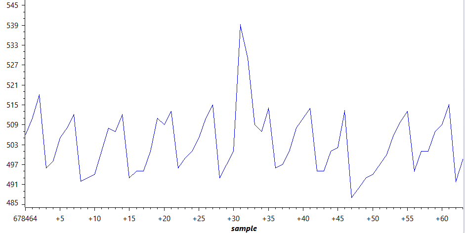
Can you please help me to figure out whats wrong or how can I get something similar to sqaure wave as an output in array, because my project involves calculation of FFT after getting that array.
And one more question, can I just change the buffer size to like 128,256 or high to get large buffer size or do I also have to change some uDMA part of the code also?
Regards,
Harshul Agarwal


