Other Parts Discussed in Thread: MSP432E401Y, MAX3223, UNIFLASH
Hello friends!
I had posted previously at TI Customer Support Chat (Case No.: CS0419030), and mister Jonathan Navor answered, that “this needs to discuss to our next level of support”. He gave me the link https://e2e.ti.com/p/addpost in order to connect me to an experienced Engineering Applications Specialist according to the product line. So I repeat my posts. I have two questions.
I use MSP-EXP432E401Y Evaluation Board, I write in Code Composer Studio an assembly code. I use the integrated USB D-bug adapter of MSP-EXP432E401Y usually in SWD mode.
The first one (the most important question).
Accidently I locked my microcontroller with switching core clock to the MOSC, which was fully disabled. I can describe my steps in detail.
1) I didn’t change the reset value of MOSCCTL Register. Its reset value is 0xC. It means that:
a) MOSC circuit is powered down;
b) Main oscillator circuit is powered down.
2) I set 0x03 into bit-field OSCSRC of the RSCLKCFG Register. It means MOSC is the oscillator source. But MOSC is fully disabled! It was my fatal mistake. I have been programmed 8-bit microcontrollers and configured their clock-circuits and PLL many times, so I’m very sad due to my stupid mistake.
3) The microcontroller actions in this case are controlled with bit MOSCIM (reset value is 0) of MOSCCTL Register: “Regardless of the action taken, if the MOSC fails, the oscillator source is switched to the PIOSC automatically. If the MOSC fails, a MOSC failure reset is generated and reboots to the NMI handler” [SLAU723A–October 2017–Revised October 2018, page 238].
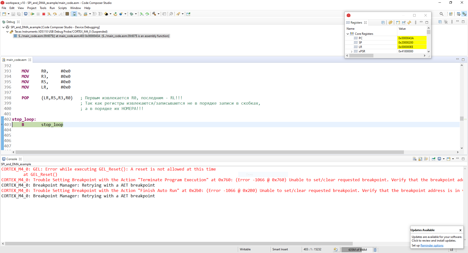
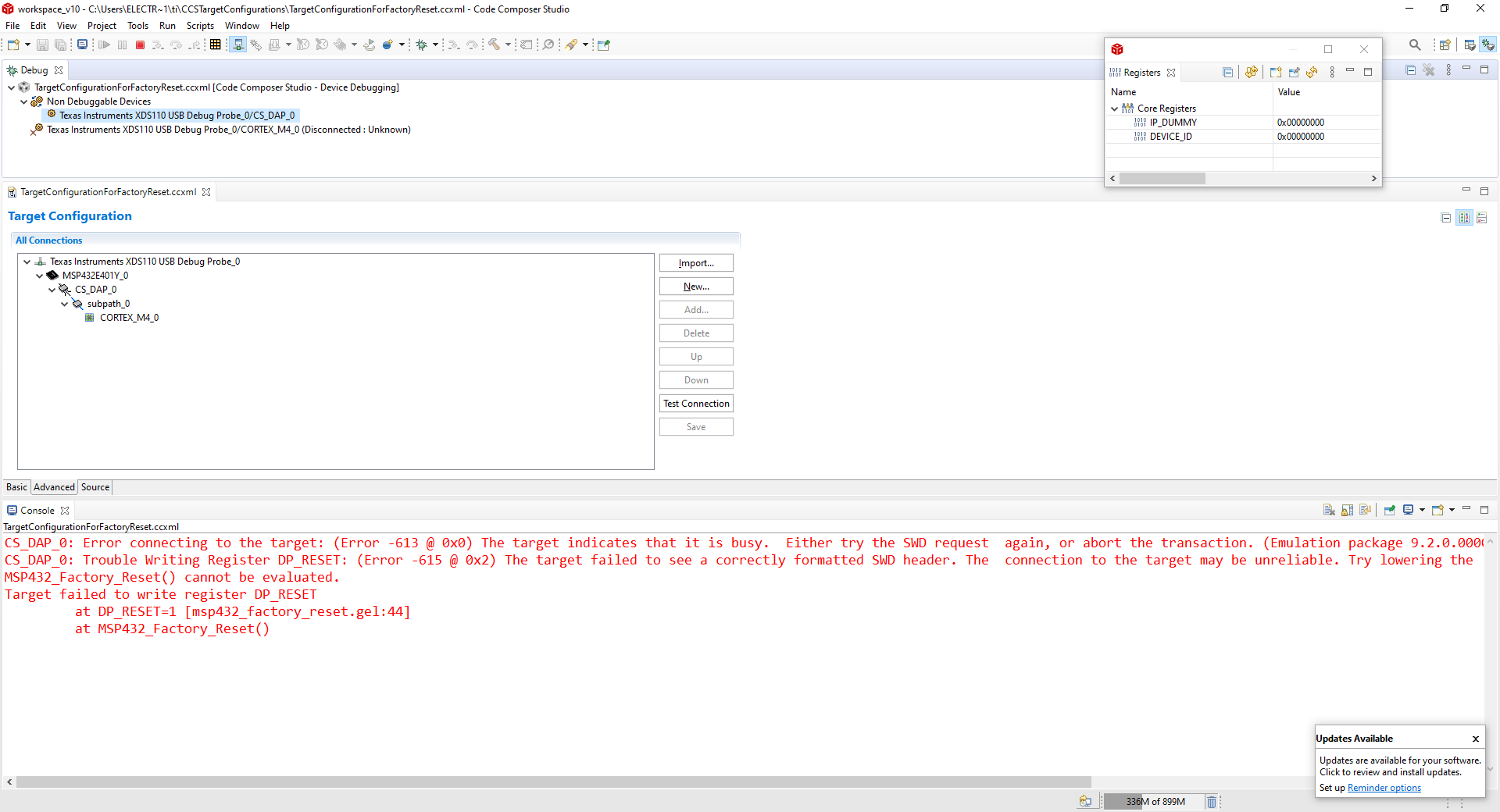
So, my microcontroller falls in reset again, again and again. The D-bugger lost the connection with microcontroller after step (2). And I can’t load new code into the device again and I can’t connect to it. When I start debugging, I see the error:
“CORTEX_M4_0: Error connecting to the target: (Error -613 @ 0x0) The target indicates that it is busy. Either try the SWD request again, or abort the transaction. (Emulation package 9.2.0.00002)”
I have made the steps described in the post below:
https://e2e.ti.com/support/microcontrollers/msp430/f/166/p/508198/1854733#1854733
But it does not help. I see the same error. I’ve made some screen-shorts, and I attach them to my post.
Script for Factory Reset:
Script for factory reset with password

Scrip for factory reset with password (Reboot_Reset)
Script for memory erase
And I noticed, when I added the script (gel-file) "msp432 factory reset" for the first time, it was shown as "memory erase". But after that, when I added this gel-file again, it was shown as "factory reset".
I have already posted this question (Case No.: CS0418250). As I have yet no response, I’m looking for other ways to solve my problem.
The second question is connected with the first one. I tried to unlock the MSP432E401Y with its Boot-loader interface. Below I’ll repeat my previous post (Case No.: CS0419030):
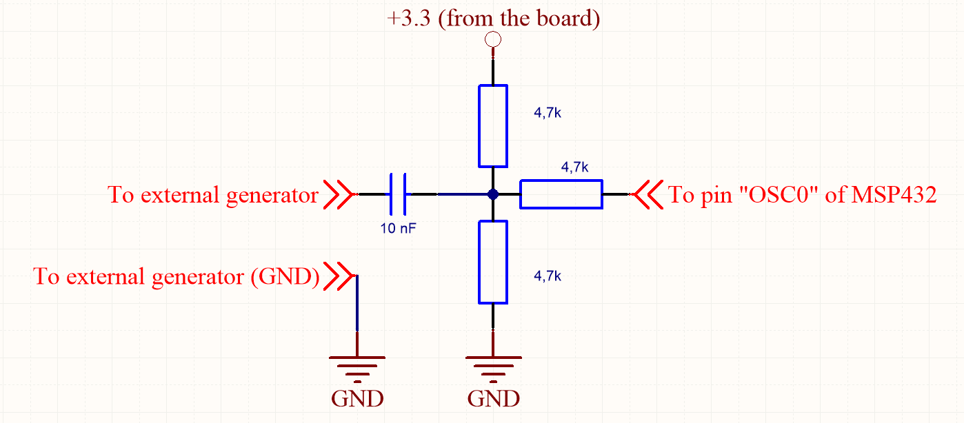
I have simple RS232-to-UART bridge based on MAX3223. I connected one cable into my PC and another one into BSL port of MSP-EXP432E401Y. I had set 0-resistors R5 and R6 to choose the UART. But I do not know, what am I to do with reset-pin?
So, I think logically: UART connects to pins PA0 and PA1; they may be already used in main user code (configured as o/i, connected to periphery etc.); so a bootloader is to stop acting of user code before the code starts; the only way to do it – is reset the device. But can the microcontroller be loaded when it is in hardware reset?
So I want to learn acting of reset pin during UART-bootloader session. And what happened, when pins for the bootloader interface are configured as GPIO?
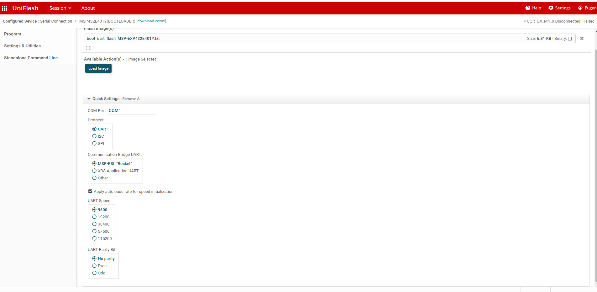
I have tried to load an image with UniFlash, but my device does not response (I tried to load holding the microcontroller in hardware reset or without the holding). With a scope I see the impulses coming from PC, but the microcontroller continue to be silent.
Please answer my questions, if it may. And I would like to say I’m really happy, that TI has the Customer Support Service.
And one more thing. Mister Jonathan Navor asked me “Once you have posted, please share with me the link so I could follow-up our product specialist for you to have the fastest response”. But now I can’t open my previous case, as I changed email address in my TI account. I had a personal email address but with that address I could not send the additional post (https://e2e.ti.com/p/addpost), as I saw the error “non-corporative email address”. I changed the personal address to corporative one, but when I try to open my case, I see “Requested record not found”. Please, say to mister Navor about my new post.