This thread has been locked.

If you have a related question, please click the "Ask a related question" button in the top right corner. The newly created question will be automatically linked to this question.

CCS/SW-EK-TM4C1294XL: Differents results between step over and step into (I2C)

Part Number: SW-EK-TM4C1294XL

Tool/software: Code Composer Studio

I'm writing some test code for a test signal generator. I'm generating analog voltage with a MCP4725 chip (will use a MCP4728 later). I write the 12-bit value I want to the chip register and expect to read the same when I read it later, however, this is to the case.

It works when I step into my MCP4725SendReceive function, but not when I step over.

Any ideas? I tried a lot of delays everywhere.


#include <stdint.h> #include <stdbool.h> #include "driverlib/fpu.h" #include "driverlib/gpio.h" #include "driverlib/i2c.h" #include "driverlib/pin_map.h" #include "driverlib/rom.h" #include "driverlib/sysctl.h" #include "driverlib/uart.h" #include "inc/hw_gpio.h" #include "inc/hw_ints.h" #include "inc/hw_memmap.h" #include "inc/hw_sysctl.h" #include "inc/hw_types.h" #include "utils/uartstdio.h" //***************************************************************************** // // System config. // //***************************************************************************** uint32_t g_ui32SysClock; // holds the main clock speed //***************************************************************************** // // Init UART interface 115200bps, 8, N, 1 // //***************************************************************************** void InitUART(void) { SysCtlPeripheralEnable(SYSCTL_PERIPH_GPIOA); while(!SysCtlPeripheralReady(SYSCTL_PERIPH_GPIOA)) { } GPIOPinConfigure(GPIO_PA0_U0RX); GPIOPinConfigure(GPIO_PA1_U0TX); SysCtlPeripheralEnable(SYSCTL_PERIPH_UART0); while(!SysCtlPeripheralReady(SYSCTL_PERIPH_UART0)) { } UARTClockSourceSet(UART0_BASE, UART_CLOCK_PIOSC); GPIOPinTypeUART(GPIO_PORTA_BASE, GPIO_PIN_0 | GPIO_PIN_1); UARTStdioConfig(0, 115200, 16000000); } //***************************************************************************** // // Init the DAC chip // //***************************************************************************** void MCP4725Init(void) { UARTprintf("Initiating.\n"); SysCtlPeripheralEnable(SYSCTL_PERIPH_GPIOD); while( !SysCtlPeripheralReady(SYSCTL_PERIPH_GPIOD) ); GPIOPinConfigure(GPIO_PD0_I2C7SCL); GPIOPinConfigure(GPIO_PD1_I2C7SDA); GPIOPinTypeI2CSCL(GPIO_PORTD_BASE, GPIO_PIN_0); GPIOPinTypeI2C(GPIO_PORTD_BASE, GPIO_PIN_1); SysCtlPeripheralDisable(SYSCTL_PERIPH_I2C7); SysCtlPeripheralReset(SYSCTL_PERIPH_I2C7); SysCtlPeripheralEnable(SYSCTL_PERIPH_I2C7); while(!SysCtlPeripheralReady(SYSCTL_PERIPH_I2C7)) { } I2CMasterGlitchFilterConfigSet(I2C7_BASE, I2C_MASTER_GLITCH_FILTER_8); I2CMasterInitExpClk(I2C7_BASE, g_ui32SysClock, false); } //***************************************************************************** // // Update the DAC output and then read back the output register // //***************************************************************************** uint16_t MCP4725SendReceive(uint16_t loadvalue) { uint8_t pui8WriteData[2]; uint8_t pui8ReadData[5]; uint16_t readvalue; // // Write the desired value to the DAC register // see mcp4725 datasheet section 6.1.1 // pui8WriteData[0] = (uint8_t) ( (loadvalue >> 8) & 0xF ); pui8WriteData[1] = (uint8_t) (loadvalue); I2CMasterSlaveAddrSet(I2C7_BASE, 0x62, false); I2CMasterDataPut( I2C7_BASE, pui8WriteData[0] ); // 1st byte I2CMasterControl(I2C7_BASE, I2C_MASTER_CMD_BURST_SEND_START); // start send while(I2CMasterBusy(I2C7_BASE)); // wait until done if ( I2CMasterErr(I2C7_BASE) != I2C_MASTER_ERR_NONE ) // check if error { UARTprintf("I2C error\n"); } I2CMasterDataPut( I2C7_BASE, pui8WriteData[1] );// 2nd byte I2CMasterControl(I2C7_BASE, I2C_MASTER_CMD_BURST_SEND_FINISH);// start send while(I2CMasterBusy(I2C7_BASE)); // wait until done if ( I2CMasterErr(I2C7_BASE) != I2C_MASTER_ERR_NONE ) // check if error { UARTprintf("I2C error\n"); } //ROM_SysCtlDelay(100000000); // tried to put a big delay here, it doesn't change the result // // Read the registers from the chip. // See mcp4725 datasheet section 6.2 // I2CMasterSlaveAddrSet(I2C7_BASE, 0x62, true); // byte 2 of figure 6.3 (actually, the 1st to be read) I2CMasterControl(I2C7_BASE, I2C_MASTER_CMD_BURST_RECEIVE_START); while(I2CMasterBusy(I2C7_BASE)); pui8ReadData[0] = I2CMasterDataGet(I2C7_BASE); if ( I2CMasterErr(I2C7_BASE) != I2C_MASTER_ERR_NONE ) UARTprintf("I2C error\n"); // byte 3 of figure 6.3 I2CMasterControl(I2C7_BASE, I2C_MASTER_CMD_BURST_RECEIVE_CONT); while(I2CMasterBusy(I2C7_BASE)); pui8ReadData[1] = I2CMasterDataGet(I2C7_BASE); if ( I2CMasterErr(I2C7_BASE) != I2C_MASTER_ERR_NONE ) UARTprintf("I2C error\n"); // byte 4 of figure 6.3 I2CMasterControl(I2C7_BASE, I2C_MASTER_CMD_BURST_RECEIVE_CONT); while(I2CMasterBusy(I2C7_BASE)); pui8ReadData[2] = I2CMasterDataGet(I2C7_BASE); if ( I2CMasterErr(I2C7_BASE) != I2C_MASTER_ERR_NONE ) UARTprintf("I2C error\n"); // byte 5 of figure 6.3 I2CMasterControl(I2C7_BASE, I2C_MASTER_CMD_BURST_RECEIVE_CONT); while(I2CMasterBusy(I2C7_BASE)); pui8ReadData[3] = I2CMasterDataGet(I2C7_BASE); if ( I2CMasterErr(I2C7_BASE) != I2C_MASTER_ERR_NONE ) UARTprintf("I2C error\n"); // byte 6 of figure 6.3 I2CMasterControl(I2C7_BASE, I2C_MASTER_CMD_BURST_RECEIVE_FINISH); while(I2CMasterBusy(I2C7_BASE)); pui8ReadData[4] = I2CMasterDataGet(I2C7_BASE); if ( I2CMasterErr(I2C7_BASE) != I2C_MASTER_ERR_NONE ) UARTprintf("I2C error\n"); readvalue = pui8ReadData[1] << 4 | pui8ReadData[2] >> 4; // register D11..D0 return( readvalue ); } //***************************************************************************** // // Main // //***************************************************************************** int main(void) { uint16_t writeMillivolts = 0; uint16_t readMillivolts = 0; FPUEnable(); FPULazyStackingEnable(); g_ui32SysClock = SysCtlClockFreqSet((SYSCTL_XTAL_25MHZ | SYSCTL_OSC_MAIN | SYSCTL_USE_PLL | SYSCTL_CFG_VCO_480), 120000000); InitUART(); UARTprintf("\033[2J\033[H"); UARTprintf("CAN Sensors Simulator (CSS) starting.\n"); MCP4725Init(); while(1) { UARTprintf("Writing DAC with %d mV\t ", writeMillivolts); readMillivolts = MCP4725SendReceive( writeMillivolts ); UARTprintf("Reading %d mV from DAC\n", readMillivolts); if (writeMillivolts > 4095) { writeMillivolts = 0; } else { writeMillivolts += 128; } ROM_SysCtlDelay(8000000); } return 1; }

  • Hello Fabrizio,

    Hard to say based on the description alone. I would recommend using an oscilloscope (or logic state analyzer) to compare the signals and see what might be going on. Without an oscilloscope capture, it will be hard to tell what may be occurring.

    You may need to consult the device datasheet to see if there is any setup time or save time for how long it takes the register values to be processed and be ready to be read out. Also you mention you tried a lot of delays everywhere but that doesn't say much... what's the longest value delay you tried? What kinds of areas did you use delays at and why?

    Again, oscilloscope would be handy here to see where the stepping through code was needed to take long enough for certain actions to work.

    Also obligatorily must confirm if you are using pull-up resistors on SCL/SDA and what their values are. If you got a valid response I want to assume you have these and are using good values, but still want to verify.
  • Hi Ralph,

    Follows a direct quote from poster: "It works when I step into my MCP4725SendReceive function, but not when I step over."

    Note that "success" is claimed when code is, "stepped into" - but not when "stepped over!"     That's to be expected - is it not?    (When "stepping over" - is it not likely that key code blocks will not execute - causing poster's issue?)

    Poster may have intended "Normal Code Run" - instead of, "Stepping Over. "    (I believe that was your conclusion.)

    It is not hard to accept that "Stepping Over" code (depending upon what's been bypassed) - will reduce and/or prevent the program's full/proper operation...     In my (near) 10 years @ this forum - I cannot recall a (similar) complaint attributed to, "Stepping Over!"     (again - this appears to be a language issue - poster (most likely) meant that his, "program fails when RUN!")

  • Thinking further of "Poster's (likely) code failure when RUN" - follows a standard test methodology:

    • Identify then Insert "break-points" just after each "major" code block
    • Run the code at normal speed - then note key (peripheral) register contents
    • Should those contents "meet expectation" log that fact
    • Remove that particular break-point
    • Run the code again (this time code stops @ break-point #2 (further w/in the code)
    • Again observe register content for correctness

    In many cases (we've observed) certain code blocks will execute correctly - others may fail.    

    This "identification" allows a "pin-pointing" (or focus) upon those code blocks which (may) require added delay - or (better still) waiting for a particular "function call" to properly complete.

    Note too that the "test/verify" process is made more complex as both user's MCU AND external/connected device - must be managed w/full specification compliance.   (thus the importance of breaking each code-run analysis into small, logical parts!)

    The above is a clear demonstration of "KISS" (mysteriously (and mistakenly) banned here) and which proves of immense, on-going value (especially here) during design & development...

  • Thanks guys,

    I'll try the oscilloscope first, then the break-points. I think I'll see something at the oscilloscope, as the output voltage follows what I read and not what I write. It should be something in the write phase.

    I have 4k7 pull ups, 10cm (4in) of cable on my proto. And yes, it fails when I just "RUN" the software.

    This is my test code and circuit for something more complicated, with several other peripherals. I'm testing one by one before putting all together, I2C, SSI, PWM, Timer, CAN, GPIO. 

    I'll come later with the oscilloscope, I think I'll see something weird.

  • Hi cb1,

    I think the reason might be that when Fabrizio single-steps into the function it gives enough time for the I2C to become busy after the I2CMasterControl() is called before reaching the next statement while( I2CMasterBusy(I2C7_BASE) ). When he steps over the function the code will fail the while( I2CMasterBusy(I2C7_BASE) ) as the I2C is not yet busy.

    Per recommendation from you and Amit in the past it is to replace:

    while( I2CMasterBusy(I2C7_BASE));

    with:

    while(!( I2CMasterBusy(I2C7_BASE)));

    while( I2CMasterBusy(I2C7_BASE));

    I think Fabrizio can try it and see if it makes a difference.
  • Charles,

    QUITE a GOOD GET by you, Sir!    (I missed that completely - dummkopf!)

    Amit receives full credit for that (cb1 zero) - that "indirection" was all his.    (firm/i avoid the 129 (WAY too SLOW!)

    That said - the ability to RUN Code - and "Selectively Break" (at strategic points) PURE KISS - proves IMMENSELY USEFUL.    (though banned here - especially though banned here!)

  • Hi Charles,

    Thanks for the suggestion, I too forgot about that particular step with I2C. Hopefully it will be soon embedded permanently in my head to always look for that.

    Hi cb1,

    Just for clarity, I was indeed making my suggestion based on the idea that Stepping Over was synonymous with Running the code. Hence the focus on what delays were used as well as getting an o-scope which would provide a look at the timings and where delays were helping versus not.

    Also I am not 100% sure but it sounded like were you suggesting that Step Over function skips code execution inside function entirely? I don't think that is the case, rather it just doesn't bring you into the function for line by line debug inside the function but just runs the function at normal speed and then brings you to the next function. Kind of like a pseudo-breakpoint. I would need to verify that but that's been my understanding of 'Step Over' for years now so I'd be quite stumped if that was false.

    The breakpoint method certainly works well for debug as well if you don't have access to a quick o-scope, but in my experiences thus far with SPI (especially so) and I2C I find just looking at the data/clock lines tremendously quicker at problem identification and equally or more useful and thus my preferred suggestion for debug when possible. I've spent far more hour trying to guess blindly what may be going wrong for SPI/I2C issues than needed as each and every time a well marked o-scope or Saleae Logic State Analyzer capture was provided the answer became very apparent without guesswork. :)
  • Hi Ralph,

    As long time "IAR" user - I'll have to check to see if I've "butchered" the code handling via, "Step Over." (we always & only use IAR - as clients (rightly) demand that we work w/multiple vendor MCUs - single vendor can NEVER (always) prove best/brightest!)

    As to scope over breakpoints - poster DID report (some) I2C success! That - in my book (most of the time) indicates that the "signal basics" (may) be correct. And shifts the "blame" to the more complex - code issues.

    It is agreed that (both) methods - used in combination - prove best. Worst case scenario may "work in the lab" (just barely) and then fail short time later - while "in the field."
  • Thanks a lot Charles, Ralf, cb1, Amit

    The main issue was not this, but after solving it, your hint avoided other problem (messages with one one byte insted of 2).

    The things I saw wrong on the scope were:

    1- Me. I was sending 1 more byte that I should, and in the wrong position. I don't know how it still worked when I stepped over, I think I will take a look at this later.

    2- Even if I send a constant data every time, the data appearing on the scope was changing all the time in a counter way in the 1st byte after the address. This happens (I believe) because the I2C chip accepts more data after the stop to keep updating the DAC output, at least this is what I could understood reading one more time the datasheet.

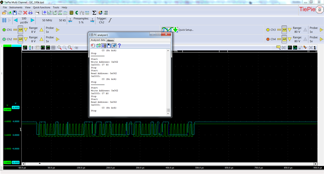
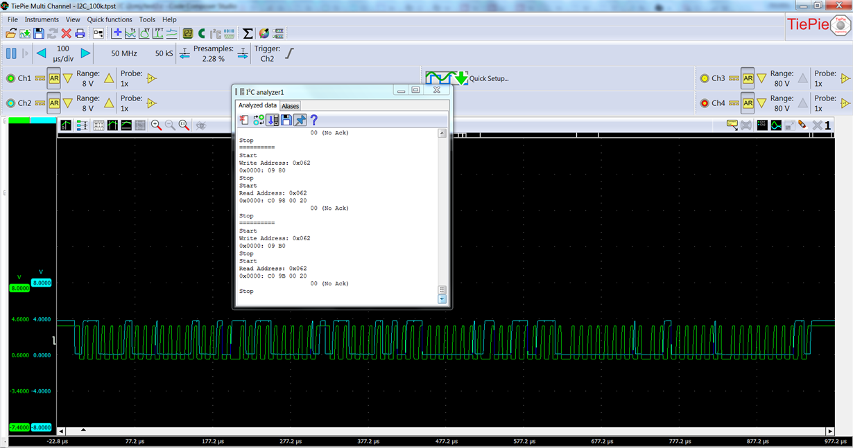
    Now I need to take a look at the scope prints, to understand exactly the relation with the received messages, what I see on the Tiva is not what the software of my PC scope reads.

    Next step is to try to write a "driver" for this chip using i2cm_drv.c provided in sensorlib.

    Not working

    Working

  • Ralph Jacobi said:
    I am not 100% sure but it sounded like were you suggesting that Step Over function skips code execution inside function entirely?

    The addition of "entirely" is Ralph's invention (not mine) as this quote reveals: "is it not likely that key code blocks will not execute" - causing poster's issue?    "Entirely" is a misstatement of fact!

    While this writing (via IAR's "Help") is not as definitive as I'd like - it DOES provide (some) cover.   (i.e. "without entering!")    Devil "lies" w/in IAR's interpretation and/or handling of: "next statement, function call, or instruction!"    Should our poster have employed (any) "standard C" (quite possibly via the API) it appears that certain code may NOT be executed!     At least - there is (some) element of risk!

    The power of a "real/Pro, vendor agnostic, substantial IDE" (i.e. IAR) is teased, below:      (reliance upon "handling of functions" by far lesser IDEs  is (unlikely) to create/justify a "general ruling...")

  • Hi cb1,

    Quite interesting! Subtle differences with compilers. The CCS expert I know who I happened to talk with earlier today did confirm I was accurate about code execution for "Step Over" for CCS though. Good to know that IAR doesn't quite work the same though, that may be valuable for future posts so thanks for sharing!!
  • Hi Ralph,

    I was seated - rather often - in the "back of NYC public school classrooms" - for good reason.  (punishment)     So - when challenged - "horse's mouth" (IAR Help) to the rescue.

    Indeed there ARE differences - some subtle - some not so!    (IAR has (forever) supported SWD - don't believe CCS has (yet) to reach that (GPIO liberating) goal!     And of course - the ability to move quickly/efficiently/freely among multiple ARM vendors - cannot be understated!)

    I recalled the "time-savings" resulting when we, "Stepped Over" those functions (known to be good) which took "too long" to execute!     Had the code "fully executed" - we'd (still) be testing...

    Yet - issue here was NEVER "Stepping Over" - poster intended "RUN" - which both you/I detected... (and freed from that "detection" - Charles provided the "solution" ... ...although there are conditions in which that (pardon) bit contrived, "repetitive/inverted busy check" has been PROVEN to FAIL)

  • Hi cb1,

    Oh yes, definitely agree the intent is to run. Just figured we should close the loop for any future readers in addition to OP's summary of his solution! :)