This thread has been locked.

If you have a related question, please click the "Ask a related question" button in the top right corner. The newly created question will be automatically linked to this question.

CCS/SW-EK-TM4C1294XL: need help with PCF8574AT i2c (16x2)LCD controller with tm4c2194xl

Part Number: SW-EK-TM4C1294XL

Tool/software: Code Composer Studio

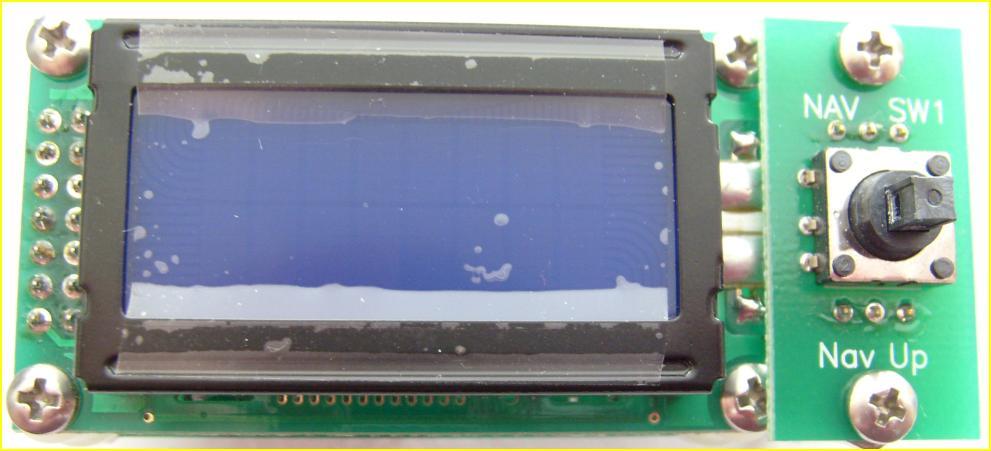
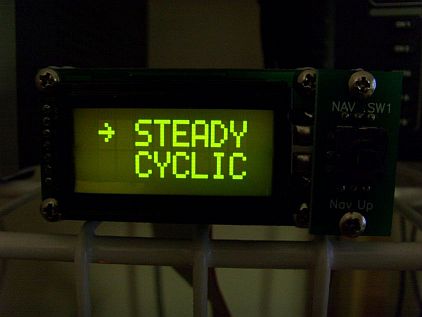
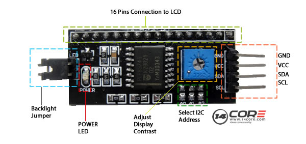
i have been trying to interface the 16x2 lcd with my tm4c1294 launchpad but i'm unable to make any progress tried lots of address as mentioned in many pages but no luck.

please help!!

  • Rohan Parvatiyar said:
    i'm unable to make any progress - tried lots of address as mentioned in many pages - but no luck.

    While "feeling your pain" - the description,  "unable to make any progress" proves (very) vague - does it not?

    The powerful  "Development & Diagnostic" Technique  "KISS"  provides  helpful  "specifics"  - which guide & inform your actions.     Several follow:

    • you note  "PCF8574AT" as (both)  I2C based & capable of  "LCD Control."     Are both capabilities confirmed?     (it is preferred that poster's (link) to such devices - reducing excess demands upon "helpers.")
    • have you "scoped" - or otherwise confirmed - that your MCU is outputting the I2C signals - both SDA & SCL?
    • and - have you confirmed those (same) signals - safely arriving - at your  "PCF" device?
    • have you employed (proper, external) pull-up resistors (10K suggested) upon both SDA/SCL?
    • have you "ohmed out" your connections between "PCF" and the "2x16 char Lcd?"    (assumes that the "PCF" is NOT resident w/in that display)
    • is the "PCF" compatible w/the 3V3 signal levels - produced by your MCU?     Usually this will NOT prove the case should the "PCF" be powered by 5V.    (varies - on a case by case, basis)
    • should "all of the above" prove correct/true - is your software properly configuring the "PCF?"     These chips usually include a "Command-Control" byte(s) - which must be properly written - to enable correct operation.     Note that you MUST supply the proper I2C Address to the "PCF" - to have ANY chance at success.     (scope confirmation proves ideal for this task)

    It is hoped that this brief guide will enable,  "some progress"  to arrive.    

    Do note the value & power provided by "KISS" - and its systematic - "one (measurable) step at a time" - focused probing.

  • Hi,
    cb1 provided very good tips for you to diagnose your problem and the best of which is to use the scope to capture your bus activities. Make sure you have pullup resistors on the SDA and SCL bus as noted by cb1.

    The PC8574AT is an 8-bit I/O expander for I2C bus. Is your problem between the MCU and the I/O expander or between the I/O expander and your LCD?
  • Greetings Charles,

    Still "on the road" - but today @ (near) sea-level.    Poster described the "PCF" as "LCD Controller" - and not providing a link - I accepted his description.

    Now - as you've made the effort to discover the "PCF's" real functionality (i.e. 8-bit Port expander) - I note a caution.      Poster's Char-based Lcd includes an 8-bit data bus (accommodated by the PCF expander) - yet  TWO ADDITIONAL "COMMAND SIGNALS" (RS & R/W) - are required!      Thus - the objective of "I2C to LCD" - may have  "Fallen off - poster's tree!"

    These Char LCDs (may) operate via 4-bit data bus - yet the complexity is (then)  raised an "order of magnitude higher" - and that difficulty is greatly MAGNIFIED - when (both) the "PULSING "E" Signal" (and RS) must be embedded w/in that same,  PCF expander.

    Poster's (superior) choice - if ONLY I2C (or SPI) interface (to the Lcd) is desired -  is a, "16-bit (not 8-bit) Port Expander."       (with the LCD operated in the safer, faster, more robust,  8-bit data mode!)

    May it be noted that,  "Rather than (pedestrian) "Scope Use" - many would (surely) award "BEST" to  the "Proper,  SOLUTION-GUIDING,  PROCESS KISS!"     (even though - especially though - KISS (appears) banned here ... leading to: "Tortured, ineffectual, non-memorable/unknown, multi-phrased substitutes!"     Pity!)

  • Hi cb1,
    That is a good insight on the 16x2 LCD needing the RS and R/W signal for 10 I/Os if not operated via the 4-bit bus which would have complicated the LCD interface. I remember you mentioned the same thing in another post a while back.
  • Thank you, Charles - indeed.       You surely know - but others should  "be mindful"  that the,  "Employ of an 8-bit Port Expander"  comes at the cost of 2 GPIO (and 4 GPIO - if the expander is SPI based  [many are]) - thus 25% of the "expansion" is devoured via the MCU <-> Expander Interface.      Such proves yet (another) reason why firm/I most always choose the 16-bit Port Expanders.    

    Note that the Signal LOSS - when employing an 8-bit Port Expander - via SPI - is especially grievous.    (4 pins lost yields (only) 4 pins of net gain!)     NOT too useful...

    Dawns that those here may enjoy seeing my firm's creation of  (what's believed) to be the world's smallest,  "Intelligent  I/O Module -  including Native:  I2C, SPI, CAN, UART & USB Interface."    (that "well attached" (PROTOTYPE shown)  "5-Way NAVigation Switch" - comfortably, efficiently & compactly satisfies - the "Input Aspect" of  this "giant client's" desired I/O module...)

    and "illuminated" (for viewing w/in "dark ambients")

    While "small" - NOT to doubt the power of such a device.     Shown below - a 60 pound "Inertia Wheel" - fully  spun-controlled - via this unique I/O Module's  ARM MCU.    (used w/in Autonomous Auto,  BLDC  Motor-Controller Development)     Note the,  "NO Expense Spared Workbench" ...  that's a "defrocked Bowing Alley Lane" ... (gutters were "extra" - thus bypassed (even when "used" - especially when used - as (originally) intended.)     (extra-credit if  one  "gets that.")

    and here ...  Not quite your  "Father's  Autonomous Cars"    OR     "Sheep in Wolf's Clothing"     (cloth  "traded"  for  "hi-gloss paint & sheet-metal")

  • Sorry it was my bad that i couldn't explain my difficulty. i'm not using the PCF8574AT ic only but the i2c lcd module which is a 16 pin i/o device and is totally devoted to controlling the lcd

    the above module is the one that im using.

    please help

  • Hi Charles,

    WHAT to say?        (maybe if I "worked harder" - created a (more) detailed list - or included a photo, proving operation?)
    I cede this poster to, "you/others."

  • Sorry for the inconvinence but it would be very nice if you could help me in the situation.
    have to complete this as project!!
  • Here I copy and paste cb1's last listed tip for diagnosis.  Please report back what your I2C address on the scope? Did you have a chance to go through the PCF datasheet for the I2C slave addresses. Don't mix up between the slave address and the address byte. For example, the slave address may be 0x27 but the address byte will be either 0x4E or 0x4F depending on the write or read. The LSB is to control the direction. You should go to 14core to research your product. r

    • should "all of the above" prove correct/true - is your software properly configuring the "PCF?"     These chips usually include a "Command-Control" byte(s) - which must be properly written - to enable correct operation.     Note that you MUST supply the proper I2C Address to the "PCF" - to have ANY chance at success.     (scope confirmation proves ideal for this task)


  • Greetings Charles,

    (Very) good job!     Great & detailed efforts - now "in evidence" - by unfortunately (just) TWO here.

    It is noted that poster STILL,  "Requests HELP" ...  is not a more factual description,  "MORE  HELP?"     (telegraphs an "expectancy" - confirmed by ZERO:  "Thanks/Gratitude!")

    Would it not be "poetic" - if rather than "Thanking & Addressing YOU" - next post  (continued)  - its  (always & only) "EXPECTANCY?"      I'm done...

  • cb1_mobile said:
    Note the,  "NO Expense Spared Workbench" ...  that's a "defrocked Bowing Alley Lane" ... (gutters were "extra" - thus bypassed (even when "used" - especially when used - as (originally) intended.)     (extra-credit if  one  "gets that.")

    Newton's 1st law of motion: e.g. objects in motion tend to stay in motion unless acted on by an outside force, IE the wrist when twisted will render the motion of ball into the gutter. 

  • yes i have checked for the output from the SSDA and SCL pins and they are are working fine.
    about the pull up resistor then it is already there within the board.
    about the signalling voltage that i couldnt check because couldnt find anything over it.
  • the module includes 16 pins out of which 5 pins are directly connected to the vcc and ground pins somehow, rest 11 pins that are there is the one which require the programming. now if even if used in 4 bit mode still it is 7 pins to configure out of which Register Select and Enable pins are the ones which decide the reading or writing over the lcd.
    so somehow i'm unale to get about how am i supposed to do that!!
    thank you..
  • My friend - you've answered (some) yet not ALL - of the detailed questions presented in your behalf!       Those (unanswered) questions "Had some Basis" - and minus your adequate response - our ability to assist is lessened.

    The LCD module chosen is  (very)  "Non-Standard."     Did you select it?      If so - would it  not make far more sense to place it aside - and obtain a "Far more standard, Character Lcd Module?"

    It remains unclear to me (possibly to you - as well)  "IF the I2C implementation is "SEPARATE FROM the Lcd Interface?"      Would you be so good as to ask your instructor - or manager - if the "PCF (I2C to 8 bit parallel) chip" - is "Imposed between the LCD's data bus - and the outside world?"    (meaning that you are FORCED to employ I2C - to interface to the Lcd!)

    If you've read my earlier posts - again in your behalf - I noted that  "8-bits" is insufficient to control such Char LCD - unless ordered into 4-bit mode.       And - based upon the (extreme) brevity of your responses - and the far greater complexity "4-bit mode demands" - I see 4-bit mode as having (almost) ZERO Chance of success!      Thus - should the PCF chip be imposed between LCD & MCU - a "Hybrid Interface" has been created!    (Likely 8-bit data-bus - via I2C - and 2 command signals - via parallel - directly from MCU's GPIO.   That's both UGLY - and DEMANDING - and far beyond my desire to detail...)

    Whether it is to be myself - or vendor's Charles - to your (continued rescue) - you MUST discover & advise your help crüe - as to the "independence and/or freedom of the LCD input signals" from the PCF/I2C Port Expander!      The "method of attack" revolves heavily around that fact - and even though "many posts in" - that key data has NOT been clearly presented...

  • i checked the output of the pins at the module side and they stay high thoroughout the whole transaction time.
    hence it is too difficult to get whether im applying the correct address so for that i ran a loop from 0x00 to 0xFF , but yet i couldnt see any change in the behaviour of the lcd or the pins over the board.
    I2CMasterInitExpClk(I2C0_BASE, SysCtlClockGet(), false);//false for 100kHz mode
    I2CMasterEnable(I2C0_BASE);
    these lines were supposed to provide the clock to it and select between the master and slave, yet i see no clocking over the SCL.
    i'm very new to this board and these are the basic for me o know that why have to implement it any how.
    thank you and i appreciate your help!!
  • Perhaps our issue IS "language" - yet you (repeatedly) "Fail to respond to direct questions" - intended ENTIRELY for your BENEFIT!

    You've now presented NEW & ADDED FACTS - w/out (AT ALL) responding to, "Questions Earlier Presented!" Should any here - respond to your "newest writings" - they are contributing to the "KRAZY-MAKING" of your support crüe.

    So once more - via the "magic" of Cut & Paste:

    Whether it is to be myself - or vendor's Charles - to  (your continued rescue) - you MUST discover & advise your helper crüe - as to   the "independence and/or freedom of the LCD input signals"  from the PCF/I2C Port Expander!      IN OTHER WORDS - IS THE LCD'S DATA BUS - ACCESSED ONLY VIA I2C?  

    The "method of attack"  (to BEST ASSIST YOU) revolves heavily around that fact - and even though "many posts in" - that key data  (MANY TIMES REQUESTED)  has NEVER  been presented!

    You remain silent as to whether you've,  "Asked your instructor and/or manager" for assistance - or the Lcd Module's Vendor.     Any one - may shed needed light - and appear UNDER UTILIZED  (likely)  UNUTILIZED!

    The two "lines of I2C code" you've just provided do NOT include MULTIPLE REQUIRED I2C Function Calls - and minus those - have  NO CHANCE of producing I2C Output!    I2CMasterDataPut() is NOTABLY ABSENT!  

    Yet - we MUST stay TRUE to "KISS" - and FAR MORE FUNDAMENTAL IS LEARNING,  "IF  I2C  IS  EVEN REQUIRED" -  BY THE LCD!      THAT SHOULD BE YOUR  INTENSE FOCUS...