This thread has been locked.

If you have a related question, please click the "Ask a related question" button in the top right corner. The newly created question will be automatically linked to this question.

EK-TM4C123GXL: Sensor Hub - PWM Issues

Part Number: EK-TM4C123GXL

Hello, 

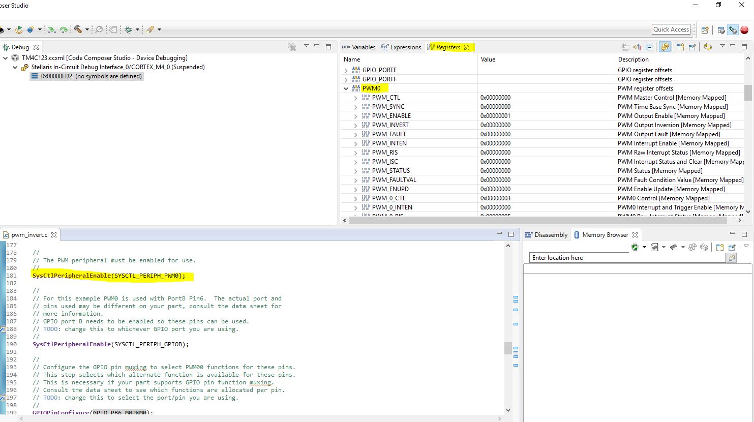
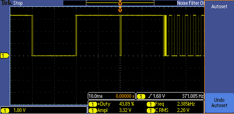
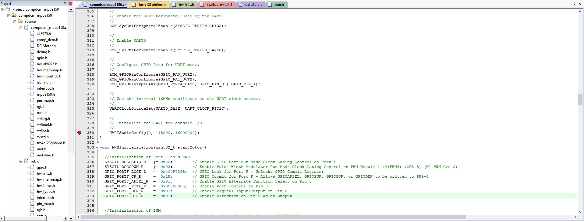
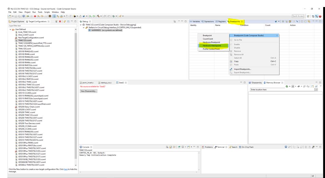
I'm currently using the TM4C123GXL with the Sensor Hub's gyroscope. However, I want to be able to use the gyroscope along with a PWM and at certain angles, produce a specific PWM output. Coding is not my issue, it's the fact that when I debug, there are no PWM registers to be evaluated. I'm using the compdcm_mpu9150 file that is included in the TI folder. 

I simply want to be able to use the gyroscope as well as the PWM. 

Has anyone else had this issue? If so, how would I enable my PWM registers so I can utilize them? 

Thank you in advance. 

Mitchell 

  • Hi Mitchell,
    If you want to use the PWM then you will need to first initialize the PWM module. I will suggest you first take a look at the PWM examples under <TivaWare_Installation>/examples/peripherals/pwm. Try to run the PWM example and get a feel for how it works and then incorporate into your sensorhub application.
  • Thank you for your response.

    As I've said, coding is not the issue. I've initialized everything properly and included the necessary files, however if you debug the program I am not able to select any PWM registers to observe. System control doesn't even show PWM registers.

  • What do you mean you can not select any PWM registers to observe? Can you take a screenshot of what you are trying to do?

    I just ran the TivaWare pwm example and I can see all the PWM registers in the register window. You need to make sure you initialize the PWM as i said before. Before you execute the SysCtlPeripheralEnable(SYSCTL_PERIPH_PWM0) there is no clock provided to the PWM module and the register window will not show any valid values but rather a red text saying 'Error: unable to read'. 

  • HI Mitchell,
    I have not heard back from you. I assume the issue is resolved. I will close this thread for now. If you have new questions you can open a new thread or you can reopen this thread if you need further resistance.
  • Hi Charles, 

    The issue was resolved when I changed my system viewer file. 

    However, now that everything is initialized correctly my PWM does not output properly when the sensor hub is attached. If I use my PWM on the LaunchPad without the sensor hub, the PWM works as coded. However, when I attach the sensor hub, I'm getting a lot of noise. Do you have any suggestions regarding that? 

    Thank you for your help thus far,

    Mitchell

  • Hi Mitchell,
    Some questions and suggestions:
    What type of noise? Is the noise on the PWM or on the snsor hub?
    Do you have scope captures to show the PWM by itself and the PWM when the sensor hub is attached?
    Can you check the voltage supply and do you see noise on the supply?
    How are you supply the power to the board? Via USB?
    Can you provide external supply to the board and do you see any differences?
  • Hi Charles,
    I'm receiving noise on the PWM output.
    I have a scope and will take screen shots to provide visual reference.
    I will check the other values and get back to you asap, thank you.

    Mitchell
  • Hi Charles, 

    I've attached screen shots of the information you had asked for. 

    PWM - without sensor hub

    PWM - with sensor hub

    Power supply (VBUS)

    For reference, I'm using PE4, which if you refer to the sensor hub data sheet, says it's not being used. I'm using the gyroscope program compdcm_mpu9150 file located in the TI libraries

    Can you offer any suggestions? 

    Thank you. 

  • Hi,
    It is not clear to me on the second and the third capture. In your scope can you do a single trigger/capture instead of continuous capture? In addition, what if you try different PWM pins?

  • I've attached more screen shots using single shot.

    I would use another port but Port E is the only one that isn't currently used. I've considered using Port F, but that means I wouldn't have a blinking light to indicate gyroscope measurements are coming in. 

  • Can you clarify what are these three new captures? Are they all with the sensohub? If you are trying to generate a periodic PWM and the waveform comes out as what is shown (i..e non-periodic PWM) then you need to find out if the PWM preload registers are incorrectly updated.
    Please try other available port and see if that is making a difference. That will be easier to debug the problem whether it is specific to PE4 only.
  • The three new captures were pictures taking from the TM4C launchpad with the sensor hub attached. 

    What concerns/confuses me is why when I used the exact same code, I get a clear 50% duty cycle with the sensor hub detached, and a distorted duty cycle when the sensor hub is attached. I want it to generate a clear 50% duty cycle. 

    I will initialize another PWM module to see if it makes any difference. 

  • Hi Charles, 

    I attempted to initialize Port F, but without any success. 

    Do you happen to have a sensor hub that you could test a PWM with? 

    Thank you,

    Mitchell 

  • Hi Mitchell,

    I don't have the sensor hub. What is wrong with PF port? Have you tried PF pins for PWM without the sensor hub? If you can get PE4 to work I think it is just matter of adapting your code to other PF pins for PWM.

    Looking at the shaded areas, you have other available pins to try for PWM. 

    Connector pin         Port Name           PWM

    J1.2                         PB5                     M0PWM3

    J1.5                         PE4                     M0PWM4

    J1.7                         PB4                     M0PWM2

    J2.4                         PF0                     M1PWM4

    J3.3                         PD0                    M0PWM6/M1PWM0

    J3.4                         PD1                    M0PWM7/M1PWM1

    J3.10                       PF1                    M1PWM5

    J4.1                         PF2                    M1PWM6

    J4.2                         PF3                    M1PWM7

    I will suggest you setup some watchpoint and make sure there is no unintentional writes to the PWM preload register if you are creating a fixed period/duty cycle PWM. Supposedly you just need to set up the PWM configuration once. If your application is intentionally altering the PWM preload register then you need to debug your code. You were saying at one time that you try to generate PWM based on the sensor input. If that is the case then you need to check your code if you are changing the PWM period and duty cycle intentionally. I think this is all I can suggest you to do. First try other pins and see if you get any differences. If the noise you were talking about is repeated on all other PWM pins then it has something to do with code.   

  • I've discovered the issue! 

    The issue seems to be coming from the UARTStdioConfig function. 

    When the value of 0 is used for the PortNum, I get all the interference. But when I used 1 or 2, the UART stops transmitting to the serial monitor. Is there anyway that I can over come this? 

  • My theory was incorrect. 

    I was able to initialize Port F, but am still having issues. 

    I disabled the UART and the problem persisted. I disabled the RGB and the problem persisted. I'm now left with the I2C on Port D, and the Interrupts on Port B. 

  • I believe I found the issue. 

    ROM_IntMasterEnable();

    This from my understanding enables all interrupts. If so, can I enable for just the peripherals I'm using? 

  • Hi Mitchell,

      Glad that you found the root cause. ROM_IntMasterEnable is used to enable the the process interrupt at a global level. If you want to individually enable/disable a specific module interrupt you want to use IntEnable() or IntDisable(). For example if you do IntEnable(INT_UART0) it will enable the UART0 interrupt to the processor. 

  • Hi Charles, 

    Unfortunately when try to disable any interrupt, the UART stops transmitting. Could you please take a look at my code and see if there is any issue? I've really only added the PWMInitialization and the first two lines in main. 

    //*****************************************************************************
    //
    // compdcm_mpu9150.c - Example use of the SensorLib with the MPU9150
    //
    // Copyright (c) 2013-2017 Texas Instruments Incorporated.  All rights reserved.
    // Software License Agreement
    // 
    // Texas Instruments (TI) is supplying this software for use solely and
    // exclusively on TI's microcontroller products. The software is owned by
    // TI and/or its suppliers, and is protected under applicable copyright
    // laws. You may not combine this software with "viral" open-source
    // software in order to form a larger program.
    // 
    // THIS SOFTWARE IS PROVIDED "AS IS" AND WITH ALL FAULTS.
    // NO WARRANTIES, WHETHER EXPRESS, IMPLIED OR STATUTORY, INCLUDING, BUT
    // NOT LIMITED TO, IMPLIED WARRANTIES OF MERCHANTABILITY AND FITNESS FOR
    // A PARTICULAR PURPOSE APPLY TO THIS SOFTWARE. TI SHALL NOT, UNDER ANY
    // CIRCUMSTANCES, BE LIABLE FOR SPECIAL, INCIDENTAL, OR CONSEQUENTIAL
    // DAMAGES, FOR ANY REASON WHATSOEVER.
    // 
    // This is part of revision 2.1.4.178 of the EK-TM4C123GXL Firmware Package.
    //
    //*****************************************************************************
    
    #include <stdint.h>
    #include <stdbool.h>
    #include "inc/hw_memmap.h"
    #include "inc/hw_ints.h"
    #include "driverlib/debug.h"
    #include "driverlib/gpio.h"
    #include "driverlib/interrupt.h"
    #include "driverlib/pin_map.h"
    #include "driverlib/rom.h"
    #include "driverlib/sysctl.h"
    #include "driverlib/uart.h"
    #include "utils/uartstdio.h"
    #include "sensorlib/hw_mpu9150.h"
    #include "sensorlib/hw_ak8975.h"
    #include "sensorlib/i2cm_drv.h"
    #include "sensorlib/ak8975.h"
    #include "sensorlib/mpu9150.h"
    #include "sensorlib/comp_dcm.h"
    #include "drivers/rgb.h"
    #include "tm4c123gh6pm.h"
    #include "pwm.h"


    //*****************************************************************************
    //
    //! \addtogroup example_list
    //! <h1>Nine Axis Sensor Fusion with the MPU9150 and Complimentary-Filtered
    //! DCM (compdcm_mpu9150)</h1>
    //!
    //! This example demonstrates the basic use of the Sensor Library, TM4C123G
    //! LaunchPad and SensHub BoosterPack to obtain nine axis motion measurements
    //! from the MPU9150.  The example fuses the nine axis measurements into a set
    //! of Euler angles: roll, pitch and yaw.  It also produces the rotation
    //! quaternions.  The fusion mechanism demonstrated is complimentary-filtered
    //! direct cosine matrix (DCM) algorithm is provided as part of the Sensor
    //! Library.
    //!
    //! Connect a serial terminal program to the LaunchPad's ICDI virtual serial
    //! port at 115,200 baud.  Use eight bits per byte, no parity and one stop bit.
    //! The raw sensor measurements, Euler angles and quaternions are printed to
    //! the terminal.  The RGB LED begins to blink at 1Hz after initialization is
    //! completed and the example application is running.
    //
    //*****************************************************************************
    
    //*****************************************************************************
    //
    // Define MPU9150 I2C Address.
    //
    //*****************************************************************************
    #define MPU9150_I2C_ADDRESS     0x68
    
    //*****************************************************************************
    //
    // Global array for holding the color values for the RGB.
    //
    //*****************************************************************************
    uint32_t g_pui32Colors[3];
    
    //*****************************************************************************
    //
    // Global instance structure for the I2C master driver.
    //
    //*****************************************************************************
    tI2CMInstance g_sI2CInst;
    
    //*****************************************************************************
    //
    // Global instance structure for the ISL29023 sensor driver.
    //
    //*****************************************************************************
    tMPU9150 g_sMPU9150Inst;
    
    //*****************************************************************************
    //
    // Global Instance structure to manage the DCM state.
    //
    //*****************************************************************************
    tCompDCM g_sCompDCMInst;
    
    //*****************************************************************************
    //
    // Global flags to alert main that MPU9150 I2C transaction is complete
    //
    //*****************************************************************************
    volatile uint_fast8_t g_vui8I2CDoneFlag;
    
    //*****************************************************************************
    //
    // Global flags to alert main that MPU9150 I2C transaction error has occurred.
    //
    //*****************************************************************************
    volatile uint_fast8_t g_vui8ErrorFlag;
    
    //*****************************************************************************
    //
    // Global flags to alert main that MPU9150 data is ready to be retrieved.
    //
    //*****************************************************************************
    volatile uint_fast8_t g_vui8DataFlag;
    
    //*****************************************************************************
    //
    // Global counter to control and slow down the rate of data to the terminal.
    //
    //*****************************************************************************
    #define PRINT_SKIP_COUNT        10
    
    uint32_t g_ui32PrintSkipCounter;
    
    //*****************************************************************************
    //
    // The error routine that is called if the driver library encounters an error.
    //
    //*****************************************************************************
    #ifdef DEBUG
    void
    __error__(char *pcFilename, uint32_t ui32Line)
    {
    }
    #endif
    
    //*****************************************************************************
    //
    // MPU9150 Sensor callback function.  Called at the end of MPU9150 sensor
    // driver transactions. This is called from I2C interrupt context. Therefore,
    // we just set a flag and let main do the bulk of the computations and display.
    //
    //*****************************************************************************
    void
    MPU9150AppCallback(void *pvCallbackData, uint_fast8_t ui8Status)
    {
        //
        // If the transaction succeeded set the data flag to indicate to
        // application that this transaction is complete and data may be ready.
        //
        if(ui8Status == I2CM_STATUS_SUCCESS)
        {
            g_vui8I2CDoneFlag = 1;
        }
    
        //
        // Store the most recent status in case it was an error condition
        //
        g_vui8ErrorFlag = ui8Status;
    }
    
    //*****************************************************************************
    //
    // Called by the NVIC as a result of GPIO port B interrupt event. For this
    // application GPIO port B pin 2 is the interrupt line for the MPU9150
    //
    //*****************************************************************************
    void
    IntGPIOb(void)
    {
        unsigned long ulStatus;
    
        ulStatus = GPIOIntStatus(GPIO_PORTB_BASE, true);
    
        //
        // Clear all the pin interrupts that are set
        //
        GPIOIntClear(GPIO_PORTB_BASE, ulStatus);
    
        if(ulStatus & GPIO_PIN_2)
        {
            //
            // MPU9150 Data is ready for retrieval and processing.
            //
            MPU9150DataRead(&g_sMPU9150Inst, MPU9150AppCallback, &g_sMPU9150Inst);
        }
    }
    
    //*****************************************************************************
    //
    // Called by the NVIC as a result of I2C3 Interrupt. I2C3 is the I2C connection
    // to the MPU9150.
    //
    //*****************************************************************************
    void
    MPU9150I2CIntHandler(void)
    {
        //
        // Pass through to the I2CM interrupt handler provided by sensor library.
        // This is required to be at application level so that I2CMIntHandler can
        // receive the instance structure pointer as an argument.
        //
        I2CMIntHandler(&g_sI2CInst);
    }
    
    //*****************************************************************************
    //
    // MPU9150 Application error handler. Show the user if we have encountered an
    // I2C error.
    //
    //*****************************************************************************
    void
    MPU9150AppErrorHandler(char *pcFilename, uint_fast32_t ui32Line)
    {
        //
        // Set terminal color to red and print error status and locations
        //
        UARTprintf("\033[31;1m");
        UARTprintf("Error: %d, File: %s, Line: %d\n"
                   "See I2C status definitions in sensorlib\\i2cm_drv.h\n",
                   g_vui8ErrorFlag, pcFilename, ui32Line);
    
        //
        // Return terminal color to normal
        //
        UARTprintf("\033[0m");
    
        //
        // Set RGB Color to RED
        //
        g_pui32Colors[0] = 0xFFFF;
        g_pui32Colors[1] = 0;
        g_pui32Colors[2] = 0;
        RGBColorSet(g_pui32Colors);
    
        //
        // Increase blink rate to get attention
        //
        RGBBlinkRateSet(10.0f);
    
        //
        // Go to sleep wait for interventions.  A more robust application could
        // attempt corrective actions here.
        //
        while(1)
        {
            //
            // Do Nothing
            //
        }
    }
    
    //*****************************************************************************
    //
    // Function to wait for the MPU9150 transactions to complete. Use this to spin
    // wait on the I2C bus.
    //
    //*****************************************************************************
    void
    MPU9150AppI2CWait(char *pcFilename, uint_fast32_t ui32Line)
    {
        //
        // Put the processor to sleep while we wait for the I2C driver to
        // indicate that the transaction is complete.
        //
        while((g_vui8I2CDoneFlag == 0) && (g_vui8ErrorFlag == 0))
        {
            //
            // Do Nothing
            //
        }
    
        //
        // If an error occurred call the error handler immediately.
        //
        if(g_vui8ErrorFlag)
        {
            MPU9150AppErrorHandler(pcFilename, ui32Line);
        }
    
        //
        // clear the data flag for next use.
        //
        g_vui8I2CDoneFlag = 0;
    }
    
    //*****************************************************************************
    //
    // Configure the UART and its pins.  This must be called before UARTprintf().
    //
    //*****************************************************************************
    void ConfigureUART(void)
    {
        //
        // Enable the GPIO Peripheral used by the UART.
        //
        ROM_SysCtlPeripheralEnable(SYSCTL_PERIPH_GPIOA);
    
        //
        // Enable UART0
        //
        ROM_SysCtlPeripheralEnable(SYSCTL_PERIPH_UART0);
    
        //
        // Configure GPIO Pins for UART mode.
        //
        ROM_GPIOPinConfigure(GPIO_PA0_U0RX);
        ROM_GPIOPinConfigure(GPIO_PA1_U0TX);
        ROM_GPIOPinTypeUART(GPIO_PORTA_BASE, GPIO_PIN_0 | GPIO_PIN_1);
    
        //
        // Use the internal 16MHz oscillator as the UART clock source.
        //
        UARTClockSourceSet(UART0_BASE, UART_CLOCK_PIOSC);
    
        //
        // Initialize the UART for console I/O.
        //
        UARTStdioConfig(0, 115200, 16000000);
    }
    
    void PWMInitialization(uint32_t startMotor){
    
    	//Initialization of Port F as s PWM
    	SYSCTL_RCGCGPIO_R 	|= 0x20;     		// Enable GPIO Port Run Mode Clock Gating Control on Port F
    	SYSCTL_RCGCPWM_R 		|= 0x02;     	 	// Enable Pulse Width Modulator Run Mode Clock Gating Control on PWM Module 1 (M1PWM4) (COL 5) (M1 PWM Gen 2)
      GPIO_PORTF_LOCK_R		=	 0x4C4F434B; 	// GPIO Lock for Port F - Unlocks GPIO Commit Register
      GPIO_PORTF_CR_R 		=	 0x1F;       	// GPIO Commit for Port F - Allows GPIOAFSEL, GPIOPUR, GPIOPDR, or GPIODEN to be written to PF4-0
    	GPIO_PORTF_AFSEL_R 	=  0x01;    		// Enable GPIO Alternate Function Select on Pin 0
      GPIO_PORTF_PCTL_R 	=  0x00000005;	// Enable Port Control on Pin 0
      GPIO_PORTF_DEN_R 		=  0x01;     	 	// Enable Digital Input/Output on Pin 0 
      GPIO_PORTF_DIR_R		=	 0x01;				// Enable Direction on Pin 0 as an Output
    
    	
    	//Initialization of PWM
    	
    	SYSCTL_RCC_R 	|=	0x00100000;    	  // Enable Run Mode Clock Config for 'USEPWMDIV'
      SYSCTL_RCC_R 	&=  0xFFF0FFFF;   		// Enable PWM Unit Clock Division to /2 
    	PWM1_2_CTL_R 	= 	0x00;       			// Re-loading down-counting mode | Page 1270
      PWM1_2_GENA_R = 	0x8C;   					// Low on LOAD, high on CMPA down | Page 1283-1284
      PWM1_2_LOAD_R = 	0x3E8;   					// Cycles count down to 0 | Page 1278
    	PWM1_2_CMPA_R = 	startMotor;     	// Count value output rises
      PWM1_2_CTL_R 	= 	0x00000001;   		// Start Generator 2
      PWM1_ENABLE_R = 	0x00000010;  			// Enable PB6/M0PWM0
    
    
      GPIO_PORTF_LOCK_R		=	 0x01; 				// GPIO Lock for Port F - Unlocks GPIO Commit Register
      GPIO_PORTF_CR_R 		=	 0xFF;       	// GPIO Commit for Port F - Allows GPIOAFSEL, GPIOPUR, GPIOPDR, or GPIODEN to be written to PF4-0
    }


    //*****************************************************************************
    //
    // Main application entry point.
    //
    //*****************************************************************************
    int
    main(void)
    {
    		uint32_t startMotor = 0x1F4;		//Initializes duty cycle to 50%
    		PWMInitialization(startMotor);	//Initializes PWM
    
    	
        int_fast32_t i32IPart[16], i32FPart[16];
        uint_fast32_t ui32Idx, ui32CompDCMStarted;
        float pfData[16];
        float *pfAccel, *pfGyro, *pfMag, *pfEulers, *pfQuaternion;
    
        //
        // Initialize convenience pointers that clean up and clarify the code
        // meaning. We want all the data in a single contiguous array so that
        // we can make our pretty printing easier later.
        //
        pfAccel = pfData;
        pfGyro = pfData + 3;
        pfMag = pfData + 6;
        pfEulers = pfData + 9;
        pfQuaternion = pfData + 12;
    
        //
        // Setup the system clock to run at 40 Mhz from PLL with crystal reference
        //
        ROM_SysCtlClockSet(SYSCTL_SYSDIV_5 | SYSCTL_USE_PLL | SYSCTL_XTAL_16MHZ |
                           SYSCTL_OSC_MAIN);
    
        //
        // Enable port B used for motion interrupt.
        //
        ROM_SysCtlPeripheralEnable(SYSCTL_PERIPH_GPIOB);
    
        //
        // Initialize the UART.
        //
        ConfigureUART();
    		
        //
        // Print the welcome message to the terminal.
        //
        UARTprintf("\033[2JMPU9150 Raw Example\n");
    
        //
        // Set the color to a purple approximation.
        //
        g_pui32Colors[RED] = 0x8000;
        g_pui32Colors[BLUE] = 0x8000;
        g_pui32Colors[GREEN] = 0x0000;
    
        //
        // Initialize RGB driver.
        //
        RGBInit(0);
        RGBColorSet(g_pui32Colors);
        RGBIntensitySet(0.5f);
        RGBEnable();
    
        //
        // The I2C3 peripheral must be enabled before use.
        //
        ROM_SysCtlPeripheralEnable(SYSCTL_PERIPH_I2C3);
        ROM_SysCtlPeripheralEnable(SYSCTL_PERIPH_GPIOD);
    
        //
        // Configure the pin muxing for I2C3 functions on port D0 and D1.
        //
        ROM_GPIOPinConfigure(GPIO_PD0_I2C3SCL);
        ROM_GPIOPinConfigure(GPIO_PD1_I2C3SDA);
    
        //
        // Select the I2C function for these pins.  This function will also
        // configure the GPIO pins pins for I2C operation, setting them to
        // open-drain operation with weak pull-ups.  Consult the data sheet
        // to see which functions are allocated per pin.
        //
        GPIOPinTypeI2CSCL(GPIO_PORTD_BASE, GPIO_PIN_0);
        ROM_GPIOPinTypeI2C(GPIO_PORTD_BASE, GPIO_PIN_1);
    
        //
        // Configure and Enable the GPIO interrupt. Used for INT signal from the
        // MPU9150
        //
        ROM_GPIOPinTypeGPIOInput(GPIO_PORTB_BASE, GPIO_PIN_2);
        GPIOIntEnable(GPIO_PORTB_BASE, GPIO_PIN_2);
        ROM_GPIOIntTypeSet(GPIO_PORTB_BASE, GPIO_PIN_2, GPIO_FALLING_EDGE);
        ROM_IntEnable(INT_GPIOB);
    
        //
        // Keep only some parts of the systems running while in sleep mode.
        // GPIOB is for the MPU9150 interrupt pin.
        // UART0 is the virtual serial port
        // TIMER0, TIMER1 and WTIMER5 are used by the RGB driver
        // I2C3 is the I2C interface to the ISL29023
        //
        ROM_SysCtlPeripheralClockGating(true);
        ROM_SysCtlPeripheralSleepEnable(SYSCTL_PERIPH_GPIOB);
        ROM_SysCtlPeripheralSleepEnable(SYSCTL_PERIPH_UART0);
        ROM_SysCtlPeripheralSleepEnable(SYSCTL_PERIPH_TIMER0);
        ROM_SysCtlPeripheralSleepEnable(SYSCTL_PERIPH_TIMER1);
        ROM_SysCtlPeripheralSleepEnable(SYSCTL_PERIPH_I2C3);
        ROM_SysCtlPeripheralSleepEnable(SYSCTL_PERIPH_WTIMER5);
    
        //
        // Enable interrupts to the processor.
        //
        ROM_IntMasterEnable();
        //
        // Initialize I2C3 peripheral.
        //
        I2CMInit(&g_sI2CInst, I2C3_BASE, INT_I2C3, 0xff, 0xff,
                 ROM_SysCtlClockGet());
    
        //
        // Initialize the MPU9150 Driver.
        //
        MPU9150Init(&g_sMPU9150Inst, &g_sI2CInst, MPU9150_I2C_ADDRESS,
                    MPU9150AppCallback, &g_sMPU9150Inst);
    
        //
        // Wait for transaction to complete
        //
        MPU9150AppI2CWait(__FILE__, __LINE__);
    
        //
        // Write application specifice sensor configuration such as filter settings
        // and sensor range settings.
        //
        g_sMPU9150Inst.pui8Data[0] = MPU9150_CONFIG_DLPF_CFG_94_98;
        g_sMPU9150Inst.pui8Data[1] = MPU9150_GYRO_CONFIG_FS_SEL_250;
        g_sMPU9150Inst.pui8Data[2] = (MPU9150_ACCEL_CONFIG_ACCEL_HPF_5HZ |
                                      MPU9150_ACCEL_CONFIG_AFS_SEL_2G);
        MPU9150Write(&g_sMPU9150Inst, MPU9150_O_CONFIG, g_sMPU9150Inst.pui8Data, 3,
                     MPU9150AppCallback, &g_sMPU9150Inst);
    
        //
        // Wait for transaction to complete
        //
        MPU9150AppI2CWait(__FILE__, __LINE__);
    
        //
        // Configure the data ready interrupt pin output of the MPU9150.
        //
        g_sMPU9150Inst.pui8Data[0] = MPU9150_INT_PIN_CFG_INT_LEVEL | MPU9150_INT_PIN_CFG_INT_RD_CLEAR | MPU9150_INT_PIN_CFG_LATCH_INT_EN;
        g_sMPU9150Inst.pui8Data[1] = MPU9150_INT_ENABLE_DATA_RDY_EN;
        MPU9150Write(&g_sMPU9150Inst, MPU9150_O_INT_PIN_CFG, g_sMPU9150Inst.pui8Data, 2, MPU9150AppCallback, &g_sMPU9150Inst);
    
        //
        // Wait for transaction to complete
        //
        MPU9150AppI2CWait(__FILE__, __LINE__);
    
        //
        // Initialize the DCM system. 50 hz sample rate.
        // accel weight = .2, gyro weight = .8, mag weight = .2
        //
        CompDCMInit(&g_sCompDCMInst, 1.0f / 50.0f, 0.2f, 0.6f, 0.2f);
    
        UARTprintf("\033[2J\033[H");
        UARTprintf("MPU9150 9-Axis Simple Data Application Example\n\n");
        UARTprintf("\033[20GX\033[31G|\033[43GY\033[54G|\033[66GZ\n\n");
        UARTprintf("Accel\033[8G|\033[31G|\033[54G|\n\n");
        UARTprintf("Gyro\033[8G|\033[31G|\033[54G|\n\n");
        UARTprintf("Mag\033[8G|\033[31G|\033[54G|\n\n");
        UARTprintf("\n\033[20GRoll\033[31G|\033[43GPitch\033[54G|\033[66GYaw\n\n");
        UARTprintf("Eulers\033[8G|\033[31G|\033[54G|\n\n");
    
        UARTprintf("\n\033[17GQ1\033[26G|\033[35GQ2\033[44G|\033[53GQ3\033[62G|"
                   "\033[71GQ4\n\n");
        UARTprintf("Q\033[8G|\033[26G|\033[44G|\033[62G|\n\n");
    
        //
        // Enable blinking indicates config finished successfully
        //
        RGBBlinkRateSet(1.0f);
    
        ui32CompDCMStarted = 0;


        while(1)
        {
    			
            //
            // Go to sleep mode while waiting for data ready.
            //
            while(!g_vui8I2CDoneFlag)
            {
                ROM_SysCtlSleep();
            }
    
            //
            // Clear the flag
            //
            g_vui8I2CDoneFlag = 0;
    
            //
            // Get floating point version of the Accel Data in m/s^2.
            //
            MPU9150DataAccelGetFloat(&g_sMPU9150Inst, pfAccel, pfAccel + 1,
                                     pfAccel + 2);
    
            //
            // Get floating point version of angular velocities in rad/sec
            //
            MPU9150DataGyroGetFloat(&g_sMPU9150Inst, pfGyro, pfGyro + 1,
                                    pfGyro + 2);
    
            //
            // Get floating point version of magnetic fields strength in tesla
            //
            MPU9150DataMagnetoGetFloat(&g_sMPU9150Inst, pfMag, pfMag + 1,
                                       pfMag + 2);
    
            //
            // Check if this is our first data ever.
            //
            if(ui32CompDCMStarted == 0)
            {
                //
                // Set flag indicating that DCM is started.
                // Perform the seeding of the DCM with the first data set.
                //
                ui32CompDCMStarted = 1;
                CompDCMMagnetoUpdate(&g_sCompDCMInst, pfMag[0], pfMag[1],
                                     pfMag[2]);
                CompDCMAccelUpdate(&g_sCompDCMInst, pfAccel[0], pfAccel[1],
                                   pfAccel[2]);
                CompDCMGyroUpdate(&g_sCompDCMInst, pfGyro[0], pfGyro[1],
                                  pfGyro[2]);
                CompDCMStart(&g_sCompDCMInst);
            }
            else
            {
                //
                // DCM Is already started.  Perform the incremental update.
                //
                CompDCMMagnetoUpdate(&g_sCompDCMInst, pfMag[0], pfMag[1],
                                     pfMag[2]);
                CompDCMAccelUpdate(&g_sCompDCMInst, pfAccel[0], pfAccel[1],
                                   pfAccel[2]);
                CompDCMGyroUpdate(&g_sCompDCMInst, -pfGyro[0], -pfGyro[1],
                                  -pfGyro[2]);
                CompDCMUpdate(&g_sCompDCMInst);
            }
    
            //
            // Increment the skip counter.  Skip counter is used so we do not
            // overflow the UART with data.
            //
            g_ui32PrintSkipCounter++;
            if(g_ui32PrintSkipCounter >= PRINT_SKIP_COUNT)
            {
                //
                // Reset skip counter.
                //
                g_ui32PrintSkipCounter = 0;
    
                //
                // Get Euler data. (Roll Pitch Yaw)
                //
                CompDCMComputeEulers(&g_sCompDCMInst, pfEulers, pfEulers + 1,
                                     pfEulers + 2);
    
                //
                // Get Quaternions.
                //
                CompDCMComputeQuaternion(&g_sCompDCMInst, pfQuaternion);
    
                //
                // convert mag data to micro-tesla for better human interpretation.
                //
                pfMag[0] *= 1e6;
                pfMag[1] *= 1e6;
                pfMag[2] *= 1e6;
    
                //
                // Convert Eulers to degrees. 180/PI = 57.29...
                // Convert Yaw to 0 to 360 to approximate compass headings.
                //
                pfEulers[0] *= 57.295779513082320876798154814105f;
                pfEulers[1] *= 57.295779513082320876798154814105f;
                pfEulers[2] *= 57.295779513082320876798154814105f;
                if(pfEulers[2] < 0)
                {
                    pfEulers[2] += 360.0f;
                }
    
                //
                // Now drop back to using the data as a single array for the
                // purpose of decomposing the float into a integer part and a
                // fraction (decimal) part.
                //
                for(ui32Idx = 0; ui32Idx < 16; ui32Idx++)
                {
                    //
                    // Conver float value to a integer truncating the decimal part.
                    //
                    i32IPart[ui32Idx] = (int32_t) pfData[ui32Idx];
    
                    //
                    // Multiply by 1000 to preserve first three decimal values.
                    // Truncates at the 3rd decimal place.
                    //
                    i32FPart[ui32Idx] = (int32_t) (pfData[ui32Idx] * 1000.0f);
    
                    //
                    // Subtract off the integer part from this newly formed decimal
                    // part.
                    //
                    i32FPart[ui32Idx] = i32FPart[ui32Idx] -
                                        (i32IPart[ui32Idx] * 1000);
    
                    //
                    // make the decimal part a positive number for display.
                    //
                    if(i32FPart[ui32Idx] < 0)
                    {
                        i32FPart[ui32Idx] *= -1;
                    }
                }
    
    //            //
    //            // Print the acceleration numbers in the table.
    //            //
    //            UARTprintf("\033[5;17H%3d.%03d", i32IPart[0], i32FPart[0]);
    //            UARTprintf("\033[5;40H%3d.%03d", i32IPart[1], i32FPart[1]);
    //            UARTprintf("\033[5;63H%3d.%03d", i32IPart[2], i32FPart[2]);
    
    //            //
    //            // Print the angular velocities in the table.
    //            //
    //            UARTprintf("\033[7;17H%3d.%03d", i32IPart[3], i32FPart[3]);
    //            UARTprintf("\033[7;40H%3d.%03d", i32IPart[4], i32FPart[4]);
    //            UARTprintf("\033[7;63H%3d.%03d", i32IPart[5], i32FPart[5]);
    
    //            //
    //            // Print the magnetic data in the table.
    //            //
    //            UARTprintf("\033[9;17H%3d.%03d", i32IPart[6], i32FPart[6]);
    //            UARTprintf("\033[9;40H%3d.%03d", i32IPart[7], i32FPart[7]);
    //            UARTprintf("\033[9;63H%3d.%03d", i32IPart[8], i32FPart[8]);
    
                //
                // Print the Eulers in a table.
                //
                UARTprintf("[PITCH%4d.%03d] ", i32IPart[9], i32FPart[9]);
                UARTprintf("[ROLL%4d.%03d] ", i32IPart[10], i32FPart[10]);
                UARTprintf("[YAW%4d.%03d]\n ", i32IPart[11], i32FPart[11]);
    
    //            //
    //            // Print the quaternions in a table format.
    //            //
    //            UARTprintf("\033[19;14H%3d.%03d", i32IPart[12], i32FPart[12]);
    //            UARTprintf("\033[19;32H%3d.%03d", i32IPart[13], i32FPart[13]);
    //            UARTprintf("\033[19;50H%3d.%03d", i32IPart[14], i32FPart[14]);
    //            UARTprintf("\033[19;68H%3d.%03d", i32IPart[15], i32FPart[15]);


            }
        }
    	}


  • Hi,

     Some comments and questions:

    • We don't support DRM (direct memory manipulation) style of coding where you code your PWMInitialization(). Please reference examples under <TivaWare_Installation>/examples/peripherals/pwm folder on how to use TivaWare API to configure the PWM module.
    • When you said if you disable the interrupt then the UART is not working, which interrupt did you disable? Your sensor hub will generate interrupt to the processor. If you disable the interrupt then there is no callback executed. Check the g_vui8I2CDoneFlag flag which is set inside a callback. If the callback is not executed then the g_vui8I2CDoneFlag is 0. Now go to the main section where if the g_vui8I2CDoneFlag is 0 then the processor is put into low power mode not executing any code until a interrupt is received to wake it from lower power mode. 

  • Hi Mitchell,
    I have not heard back from you. I assume you are able to somehow resolve the issue. If you do resolve the issue please provide some feedback to this thread so others in the community can benefit from your findings. I will close this thread for now. If you have new questions you can open a new thread.
  • Hi Charles,

    The issue hasn't been resolved. I've initialized the PWM using your advice, and the signal did change and is much more clear. However, the PWM is still changing duty cycle and frequency.
    I've included the initialization code below and I'm still baffled as to why my duty cycle is varying from 11% to 25% (which is what I want it constantly at), and a varying frequency of 5.53Hz to 6.26HZ.
    Any ideas?


    //Initialization of Port E Pin 4 as s PWM SysCtlPWMClockSet(SYSCTL_PWMDIV_1); SysCtlPeripheralEnable(SYSCTL_PERIPH_PWM0); SysCtlPeripheralEnable(SYSCTL_PERIPH_GPIOE); GPIOPinConfigure(GPIO_PE4_M0PWM4); GPIOPinTypePWM(GPIO_PORTE_BASE, GPIO_PIN_4); PWMGenConfigure(PWM0_BASE, PWM_GEN_2, PWM_GEN_MODE_UP_DOWN | PWM_GEN_MODE_NO_SYNC); PWMGenPeriodSet(PWM0_BASE, PWM_GEN_2, 64000); PWMPulseWidthSet(PWM0_BASE, PWM_OUT_4, PWMGenPeriodGet(PWM0_BASE, PWM_GEN_2)/4); PWMOutputState(PWM0_BASE, PWM_OUT_4_BIT, true); PWMGenEnable(PWM0_BASE, PWM_GEN_2);

  • Hi Charles, 

    Do you think locking the register would prevent the PWM from getting updated? If so, what commands would be needed to lock those registers? 

  • Hi Mitchel,

     What you need to do is to first find out who is updating the PWM inadvertently. There is no mechanism to lock the PWM from getting updated. To find out if the PWM's period and duty cycle are modified inadvertently you can setup watchpoint registers in the CCS debugger. For example, you are using the PWM0 PWM_GEN_2. The period is configured in the PWM2LOAD register. The PWM2LOAD register is located at address 0x400280D0. Please refer to the datasheet. The duty cycle are configured using the PWM2CMPA and PWM2CMPB registers at 0x400280D8 and 0x400280DC. Your application is supposed to only initialize these registers once. By setting the watchpoints to watch for any writes to these registers you can find out in your code when these registers are written either intentionally or inadvertently.  See below images if you are new to watchpoints. Once you setup the watchpoints and let the code run, how often to you see the CPU halted because it is hitting the watchponts? Once the CPU is halted, go to the line of code and find out why the application is writing the registers whether intentionally or inadvertently? You can also use the same method to watch if the GPIO pin muxing is altered during the course of your execution. Is it possible that the pinuxing is altered. Note that the PE4 is intended for your M0PWM4 function. If the pinmux is altered in the middle of your execution inadvertently then you can see incorrect behavior.

  • I'm attempting to do this now, however, I'm using Keil. Any guidance for doing it on Keil instead of CCS (which I've never used before).

  • Hi,
    You should consult Keil or look up their user manual on how to setup the watchpoint. Every IDE debugger will support this. The watchpoint support is provided by the processor. The debugger just needs to configure the feature. I have no knowledge of the Keil. Can't help you on this. But the idea is the same. Once you set the watchpoints in keil the CPU will halt at the specified address if the CPU attempts to write to that address. You can then find out if that write was an intended write or not.
  • Hi Charles, 

    I've removed the my PWM initialization from the file all together, yet the registers you've suggested looking into are still being updated. Are you able to load the program (the one in the TI folder without my information) and tell me when/why those registers are still being changed? 

    Thanks in advance,

    Mitchell  

  • Hi Mitchell,
    Sorry, I won't have time until next week to do any experiments. Without the PWM initialization and if you find through the watchpoints that the PWM registers are getting updated then you are almost there finding the root cause, isn't? This is part of the debugging. What is the line your code that is writing to the PWM registers? If these are unintentional code, why don't you comment them out and see if that solves the problem?
  • Hi Charles, 

    I've done as you've asked and set breakpoints and watchpoints, but the only time breakpoints are met are during initialization. As the program runs I have the watchpoints up and can see the registers change, but the breakpoints aren't being set off. 

    Is there anything else you can think of? I would be eternally grateful if you could spare some time and look into it this week, or recommend someone that could. 

    Please. 

  • Hi Michell,
    I will discuss with my colleague for some idea tomorrow.
  • Also be specific which registers change.
  • Hi Charles, 

    With regards to GPIO E, I don't initialize any interrupts and the interrupt registers are still being loaded with values.

    As for PWM, the registers you recommended to watch are being updated, as well as many more. I tried to attach a video, but the file is too large. 

  • Can you take a screenshot of the PWM0/1 registers? I simply run the compdcm_mpu9150 as is. The PWM0/1 are not even initialized. Without initialization, it means there is no clock to the PWM modules. As you can see in CCS they simply display "Error: unable to read. ". I don't understand where you are seeing the PWM registers being updated constantly.

    Did you use the compdcm_mpu9150 as is from the TivaWare library?

  • Hi Mitchell,
    I think I figure out your problem. If you were using the compdcm_mpu9150.c as is then there is below code in the while(1) loop.

    while(!g_vui8I2CDoneFlag)
    {
    ROM_SysCtlSleep();
    }

    Please comment them out to

    while(!g_vui8I2CDoneFlag)
    {
    // ROM_SysCtlSleep();
    }

    The reason for your problem is that the example code is written such that it will for data from the sensor. While waiting for data, the device is put into sleep that affects the clock going to the PWM module. Your PWM module is randomly put into sleep and hence stopping the PWM signal.

    Try the above modified code and you should see proper PWM.
  • Charles...you deserve an award...you did it! 

    I can not express how much I've appreciated your help! 

    Thank you!

  • Thank you. I could have found this issue earlier but unfortunately I have no sensorhub boosterpack until today to reproduce your finding. Sorry about that.