Hi,
I'm trying to read in 9 analog inputs using the ADC sequencers and store the data in a buffer using the uDMA. Both the sequencers work separately, but when they are configured together they begin to act funny. When two sequencers are enabled, only one of the complete sequencer gets its data to the buffer. This behavior is predictable as well. The sequencer whose data get transferred is always the sequencer initiating the ADC sequencer interrupt. For example, if I configure sequencer 0 to initiate the interrupt only sequence 0 will be seen in the buffer, but if i configure sequencer 1 to trigger the interrupt, it will be that data that is located in the buffer. Here is my code:
/* Private Variables **********************************************************/
/** @defgroup _eppc_adc_Private_Variables Private Variables
* @{
*/
/** Creates an array describing the purpose of each analog input.
*
*/
analog_inputs_t analogInputs[TOTAL_ANALOG_INPUTS];
/** Stores that values of the ADC that are transfered by the uDMA
*
*/
uint32_t u32_aInBuffer[TOTAL_ANALOG_INPUTS];
/**
* @}
*/
/* Private functions **********************************************************/
/** @defgroup _eppc_adc_Private_Functions Private Functions
* @{
*/
/* Function: functionName */
/**
* @brief Function description
* @param Function parameters
* @retval Return value
*/
/**
* @}
*/
/* Public functions ***********************************************************/
/** @defgroup _eppc_adc_Public_Functions Public Functions
* @{
*/
void adc_ss1_int_handler(void)
{
//Get interrupt status
uint32_t u32_adc0Status = MAP_ADCIntStatusEx(ADC0_BASE, true);
//Clear interrupt flag
MAP_ADCIntClearEx(ADC0_BASE, u32_adc0Status);
//Sets transfer parameters for UDMA
MAP_uDMAChannelTransferSet(UDMA_CHANNEL_ADC0 | //ADC sequence 0
UDMA_PRI_SELECT, //Uses primary data structure
UDMA_MODE_BASIC, //Performs a basic data transfer
(void *)(ADC0_BASE + ADC_O_SSFIFO0), //Source of data transfer
u32_aInBuffer, //Destination of data transfer
8); //Number of data items
//Enable UDMA channel
MAP_uDMAChannelEnable(UDMA_CHANNEL_ADC0);
//Sets transfer parameters for UDMA
MAP_uDMAChannelTransferSet(UDMA_CHANNEL_ADC1 | //ADC sequence 1
UDMA_PRI_SELECT, //Uses primary data structure
UDMA_MODE_BASIC, //Performs a basic data transfer
(void *)(ADC0_BASE + ADC_O_SSFIFO1), //Source of data transfer
&u32_aInBuffer[8], //Destination of data transfer
1); //Number of data items
//Enable UDMA channel
MAP_uDMAChannelEnable(UDMA_CHANNEL_ADC1);
}
/* Function: adc_initialize */
/**
* @brief Initializes the ADC
* @retval none
*/
void adc_initialize(void)
{
//Initialize analog input struct
//AIN0
analogInputs[0] = (analog_inputs_t){0,false};
//AIN1
analogInputs[1] = (analog_inputs_t){0,false};
//AIN2
analogInputs[2] = (analog_inputs_t){0,false};
//AIN3
analogInputs[3] = (analog_inputs_t){0,false};
//AIN4
analogInputs[4] = (analog_inputs_t){0,false};
//AIN5
analogInputs[5] = (analog_inputs_t){0,false};
//AIN6
analogInputs[6] = (analog_inputs_t){0,false};
//AIN7
analogInputs[7] = (analog_inputs_t){0,false};
//Pump Current
analogInputs[8] = (analog_inputs_t){0,false};
//Enable the ADC0 peripheral
MAP_SysCtlPeripheralEnable(SYSCTL_PERIPH_ADC0);
//Averages 64 ADC samples to provide a higher resolution measurement
MAP_ADCHardwareOversampleConfigure(ADC0_BASE, 64);
//Enable peripherals
MAP_SysCtlPeripheralEnable(AIN_PERIPH_0TO3);
MAP_SysCtlPeripheralEnable(AIN_PERIPH_4TO7);
MAP_SysCtlPeripheralEnable(AIN_PERIPH_PUMP);
//Enable analog input on gpio pins
MAP_GPIOPinTypeADC(AIN_PORT_0TO3, AIN_PIN_0 | AIN_PIN_1 | AIN_PIN_2 | AIN_PIN_3);
MAP_GPIOPinTypeADC(AIN_PORT_4TO7, AIN_PIN_4 | AIN_PIN_5 | AIN_PIN_6 | AIN_PIN_7);
MAP_GPIOPinTypeADC(AIN_PORT_PUMP, AIN_PIN_PUMP);
//Configure ADC Sequencers
MAP_ADCSequenceConfigure(ADC0_BASE, //ADC Base 0
0, //Sequencer 0 (captures up to 8 samples)
ADC_TRIGGER_TIMER, //ADC trigger is generated by a timer
0); //Sequencer priority
MAP_ADCSequenceConfigure(ADC0_BASE, //ADC Base 0
1, //Sequencer 1 (captures up to 4 samples)
ADC_TRIGGER_TIMER, //ADC trigger is generated by a timer
1); //Sequencer priority
//Configures the steps of each ADC sequence
MAP_ADCSequenceStepConfigure(ADC0_BASE, //ADC Base
0, //Sequence number
0, //Sequence order
AIN_0); //ADC channel
MAP_ADCSequenceStepConfigure(ADC0_BASE, //ADC Base
0, //Sequence number
1, //Sequence order
AIN_1); //ADC channel
MAP_ADCSequenceStepConfigure(ADC0_BASE, //ADC Base
0, //Sequence number
2, //Sequence order
AIN_2); //ADC channel
MAP_ADCSequenceStepConfigure(ADC0_BASE, //ADC Base
0, //Sequence number
3, //Sequence order
AIN_3); //ADC channel
MAP_ADCSequenceStepConfigure(ADC0_BASE, //ADC Base
0, //Sequence number
4, //Sequence order
AIN_4); //ADC channel
MAP_ADCSequenceStepConfigure(ADC0_BASE, //ADC Base
0, //Sequence number
5, //Sequence order
AIN_5); //ADC channel
MAP_ADCSequenceStepConfigure(ADC0_BASE, //ADC Base
0, //Sequence number
6, //Sequence order
AIN_6); //ADC channel
MAP_ADCSequenceStepConfigure(ADC0_BASE, //ADC Base
0, //Sequence number
7, //Sequence order
AIN_7 | ADC_CTL_END); //ADC channel and last channel in the sequence
MAP_ADCSequenceStepConfigure(ADC0_BASE, //ADC Base
1, //Sequence number
0, //Sequence order
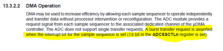
AIN_PUMP | ADC_CTL_END | ADC_CTL_IE); //ADC channel and last channel in the sequence.
//Once sequencer 1 finishes it generates an interrupt to tell the processor the FIFO is filled
//Enables ADC sequences 0 and 1
MAP_ADCSequenceEnable(ADC0_BASE, 0);
MAP_ADCSequenceEnable(ADC0_BASE, 1);
//Enables DMA for sequences 0 and 1
MAP_ADCSequenceDMAEnable(ADC0_BASE, 0);
MAP_ADCSequenceDMAEnable(ADC0_BASE, 1);
//CONFIGURE UDMA FOR ADC SEQUENCES
//Sequence 0 uDMA configuration
//Enables attribute of UDMA channel
MAP_uDMAChannelAttributeEnable(UDMA_CHANNEL_ADC0, //ADC sequence 0
UDMA_ATTR_USEBURST); //Restrict transfers to burst only mode
//Sets control parameters for UDMA
MAP_uDMAChannelControlSet(UDMA_CHANNEL_ADC0 | //ADC sequence 0
UDMA_PRI_SELECT, //Uses primary data structure
UDMA_SIZE_32 | //32bit data size
UDMA_SRC_INC_NONE | //No source address increment
UDMA_DST_INC_32 | //Destination address increment set to 32bits
UDMA_ARB_1); //Sends 8 items before bus is re-arbitrated
//Sets transfer parameters for UDMA
MAP_uDMAChannelTransferSet(UDMA_CHANNEL_ADC0 | //ADC sequence 0
UDMA_PRI_SELECT, //Uses primary data structure
UDMA_MODE_BASIC, //Performs a basic data transfer
(void *)(ADC0_BASE + ADC_O_SSFIFO0), //Source of data transfer
u32_aInBuffer, //Destination of data transfer
8); //Number of data items
//Enable UDMA channel
MAP_uDMAChannelEnable(UDMA_CHANNEL_ADC0);
//Sequence 3 uDMA configuration
//Enables attribute of UDMA channel
MAP_uDMAChannelAttributeEnable(UDMA_CHANNEL_ADC1, //ADC sequence 1
UDMA_ATTR_USEBURST); //Restrict transfers to burst only mode
//Sets control parameters for UDMA
MAP_uDMAChannelControlSet(UDMA_CHANNEL_ADC1 | //ADC sequence 1
UDMA_PRI_SELECT, //Uses primary data structure
UDMA_SIZE_32 | //32bit data size
UDMA_SRC_INC_NONE | //No source address increment
UDMA_DST_INC_32 | //Destination address increment set to 32bits
UDMA_ARB_8); //Sends 1 items before bus is re-arbitrated
//Sets transfer parameters for UDMA
MAP_uDMAChannelTransferSet(UDMA_CHANNEL_ADC1 | //ADC sequence 1
UDMA_PRI_SELECT, //Uses primary data structure
UDMA_MODE_BASIC, //Performs a basic data transfer
(void *)(ADC0_BASE + ADC_O_SSFIFO1), //Source of data transfer
&u32_aInBuffer[8], //Destination of data transfer
1); //Number of data items
//Enable UDMA channel
MAP_uDMAChannelEnable(UDMA_CHANNEL_ADC1);
//CONFIGURE INTERRUPT FOR ANALOG INPUT
//Clear the sequence 1 interrupt flag before enabling
MAP_ADCIntClearEx(ADC0_BASE, ADC_INT_SS1);
//Enable sequence 1 interrupt in peripheral
MAP_ADCIntEnableEx(ADC0_BASE, ADC_INT_SS1);
//Enable the sequence 1 interrupt in the NVIC
MAP_IntEnable(INT_ADC0SS1);
//CONFIGURE TIMER FOR TRIGGERING ADC
//Enable timer peripheral
MAP_SysCtlPeripheralEnable(SYSCTL_PERIPH_TIMER1);
//Configures the system clock as the clock source
MAP_TimerClockSourceSet(TIMER1_BASE, TIMER_CLOCK_SYSTEM);
//Configures timer as a full width periodic timer
MAP_TimerConfigure(TIMER1_BASE,TIMER_CFG_PERIODIC);
//Enables the ADC trigger output
MAP_TimerControlTrigger(TIMER1_BASE, TIMER_A, true);
//Prevent timer from counting when halted by debugger
MAP_TimerControlStall(TIMER1_BASE, TIMER_A, true);
//Load timer for 1ms frequency
MAP_TimerLoadSet(TIMER1_BASE, TIMER_A, 160000);
//Start ADC timer
MAP_TimerEnable(TIMER1_BASE, TIMER_A);
}