This thread has been locked.

If you have a related question, please click the "Ask a related question" button in the top right corner. The newly created question will be automatically linked to this question.

Vbat drain

Part Number: TM4C1297NCZAD
Other Parts Discussed in Thread: EK-TM4C1294XL

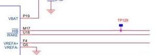
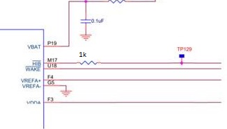
We are using TM4C1297NCZAD-212-BGA for our product and we are having issues with Hibernation module current consumption. Our product uses crystal for a hibernation module clock source and the only difference from the schematic as shown in Figure 7-2 (Tiva TM4C1297NCZAD Data Sheet, Date: June 18, 2014) is that our product does not use the 3V coin cell Battery as Input Voltage to a Switch. It uses external power source (from external rechargeable Lithium-ion battery) as an input to a Switch and HIB signal to enable Switch output.

We noticed that the Hibernation module is not in hibernation mode when the boards arrive from PCB assembly. The external rechargeable Lithium-ion battery is not present, only the Hibernation module is powered from 3V coin cell Battery, the microcontroller is not flashed/programmed. Tiva Data Sheet describes that the one of the way to enter hibernation mode is to supply power to Hibernation mode, but remove the power from Vdd. Is this desired functionality? Is there any internal MCU circuit powered from HIB signal when the signal is deasserted (~3V), that could drain 3V coin cell Battery?

  • Hello Arturas,

    You are asking about desired functionality but really that is a question for your design team to assess, is it not? The functionality we provide is certainly usable but if that behavior is what you are seeking is an assessment you need to make. From your description, I would say it certainly sounds fitting for your needs.

    You may want to read Section 7.3.8 of the datasheet about Power Control Using /HIB to fully understand that setup.

    The drain on the 3V coin cell is what is spec'd for the device in Hibernation mode in Section 27.23 Current Consumption. Look for IHIB_NORTC.

  • Thank you for your quick replay Ralph,

    Can you explain what is the sequence (what we need to configure in hibernation module?) to enter the hibernation mode when the Vdd is removed?

  • Hello Arturas,

    Reading through your initial post and looking into the Hibernation module, there is something key to clarify for your understanding.

    Hibernation mode is not active before the device is programmed. That is something you need to configure on the device via flashing it. So a blank device without any program will not be able to enter Hibernation mode.

    When programming the device, you can configure it in a variety of manners. For your use case, you'd likely want to use the Tamper feature so that the device remains in Hibernation mode until your end customer does something to wake the device to run.

    Entering hibernation mode after the device has been programmed and the hibernation module has been configured can be done with the removal of VDD when VBAT is applied, or by setting the HIBREQ bit in the Hibernation Control (HIBCTL) register.

    The device datasheet has details on all available configuration modes, and TivaWare has APIs to help set up each.

    When you determine what the right mode would be for your application, if you have specific questions about the implementation of it, then please follow-up so we can help explain in further detail.

  • Thank you Ralph for the answer,

    Is there any other circuit other than hibernation module inside microcontroller that is powered from Vbat when the microcontroller is blank? Some microcontrollers that are coming from manufacturing consumes from 30 to 100 uA from Vbat.

  • Arturas Kliop said:
    microcontroller ... powered from Vbat ... when the microcontroller is blank

    If I may - vendor has (properly) advised that the MCU's 'Hibernation Mode' (must) be specially configured - via an API programming App.

    The current draw you report does (NOT) reflect the MCU's current draw - while operating w/in 'Hibernation Mode.'   (thus appears of little use)

  • CB1 is correct. The current specifications (IHIB) for the hibernation mode are only valid when the hibernation module is properly configured. That is not done when the microcontroller is blank. The battery should not be assembled until after the microcontroller has been programmed with code that properly configures the hibernation module.

  • Thank you for answers CB1 and Bob,


    The question still stands. When microcontroller is powered from 3.3V power supply and running, Hibernation module is configured, the voltage level on HIB pin can go as low as 0.9V when the Hibernation module is active. Low voltage level correlates with high current consumption (30 - 100uA) on blank microcontroller. Is there any circuit related to HIB pin we can configure to make HIB pin voltage closer to 3.3V?

  • Arturas Kliop said:
    The question still stands.

    Does it?    Was not the earlier question, 'Why is the Current Draw higher (when the MCU enters Hibernation) than expected?      And that was answered by this reporter - and then confirmed by the MCU vendor.

    Arturas Kliop said:
    When MCU - powered from 3V3 (& running w/Hibernation module configured) - the voltage level on HIB pin can go as low as 0.9V - when the Hibernation module is active.

    Pardon - are you suggesting that the MCU's 'HIB' pin - after the MCU has been ordered into Hibernation - is providing a sufficient 'load' - to pull-down your '3V3' Hibernation source?    (that source earlier described as a Li-Ion, Rechargeable Battery.)    As our firm works regularly w/Li-Ion Batteries (and produces custom serial/parallel 'Battery Packs') it is our belief that these batteries may 'Fully Charge to 4V2!'    This sounds an alarm:

    • unmentioned is (any) 'Battery Charging Operation' - while the Li-Ion Battery is driving the 'HIB pin.'    Might you describe?
    • if indeed your Li-Ion cell(s) charges to 4V2 - is that voltage level w/in your MCU's specifications?    (i.e. for presentation to the HIB pin)
    • are your Li-Ion cells provided by a 'legitimate' Battery Producer & supplier?    If fully charged - and new - the voltage decay is FAR outside my firm's/others' experience.

    It IS possible that:

    • if the battery was 'Charged' in situ (on your board - while connected to the MCU) that ESD, a voltage spike, or (even) that charge voltage - damaged your MCU.    Low-cost Chargers are 'prone' to voltage spikes - and unless properly dissipated/limited - those spikes HAVE destroyed MCUs!    (and that 'destruction' may progress 'gradually' - as the internal damage to the MCU 'grows' - until 'notable' failure occurs.    (your report of (possible/potential) massive over-current draw via pin 'HIB' - radiates a strong scent of such transient-caused, MCU damage...)
    • or - during your earlier, 'Battery Insertion' w/out 'Ordering the MCU into Hibernation' - damage to the Battery and/or the MCU had occurred

    It would prove helpful if you'd provide the Battery's ID & spec - at least its size.   (i.e. 18650 is a 'world standard' - yet almost surely, 'too much battery' for your (hibernate) application.)

    Finally - while you report, "Voltage Level on 'HIB' @ 0V9' - nowhere is mentioned the 'Battery's Output Voltage' - at that moment!    And - that battery voltage when immediately 'disconnected & measured' from the (offending) HIB pin!    Both elements are key/critical - are they not?

    As always - once you have determined the MCU's HIB pin specifications/limitations - and insured that your circuitry is (at all times) in compliance - it proves greatly helpful to repeat such tests upon 'Fresh Boards & Batteries' - and to report those findings (in adequate detail) here..

  • Hello Arturas,

    To supplement cb1's questions regarding the battery itself:

    Arturas Kliop said:
    Low voltage level correlates with high current consumption (30 - 100uA) on blank microcontroller.

    Once again, you mention high current consumption on a blank microcontroller and I still feel there is a disconnect here. The high current consumption is expect for a blank microcontroller as it will not be in Hibernation mode. If this is the only sticking point, then the solution needs to be to the program the MCU for Hibernation mode earlier.

  • Greetings Ralph,

    I don't believe this poster has remained in the 'Blank MCU' mode.    Quote (from his post @ 05:21 earlier today):

    Arturas Kliop said:
    When microcontroller is powered from 3.3V power supply and running, Hibernation module is configured, the voltage level on HIB pin can go as low as 0.9V when the Hibernation module is active.

    Unless you have (other) reasons to 'suspect' the Blank Mode to continue - we may have 'crossed that bridge.'     I'd place my bet on (earlier) 'Damage to the MCU' - via one or several of the issues previously noted...

  • Hello cb1,

    I do hope that is the case but I haven't seen confirmation that we and Arturas are in agreement on the blank microcontroller will not be in hibernation mode and have non-Hibernation current draws. According to him, the "The question still stands." regarding the prior dialogue with blank MCU current draw.

    Arturas,

    Could you clarify if we are only talking about the voltages and currents for a properly programmed MCU that is configured for hibernation mode now?

  • Indeed he wrote, "The question still stands."     Yet - based upon his quote (today) - and first your - and then my - and then Bob's writings - he was (very) well advised that Hibernation is NOT possible w/a 'Blank MCU.'    I'm not at all convinced that his earlier question STILL STANDS - AND if it does - WHAT MORE CAN YOU, BOB OR AN 'OUTSIDER' DO?

    To my mind - the 0V9 voltage level at the 'HIB' pin - strongly suggests a damaged MCU or failed Li-Ion cell and/or related Charging hardware.

    I've provided diagnostic guidance - and further suggested that he perform (proper) tests upon a fresh board & battery.   (of course AFTER commanding the MCU into Hibernation Mode...)

  • Hi cb1,

    Agreed on all fronts. If we are past hibernation, then Arturas would benefit most from carefully reading your detailed guidance on how to diagnose the 0.9V voltage level (which is why I stayed away from further suggestions on that since it's been well covered) and provide us more details about the system setup.

  • Hi Ralph,

    Always good when, 'You, Bob & outsider' are in (some) agreement.

    Indeed the Li-Ion batteries ARE a FORCE - and will last 'light-years' longer than a 'coin-cell.'    (maybe - a (slight) exaggeration.)

    It is far more 'normal/customary' to employ the Li-Ion cell (or array) as a 'Back-Up' power supply for the entire board(s) - NOT for any 'hibernate' role.

    We should note that the fully charged Li-Ion cell will (usually) output ~4V2 when fully charged - which will slowly decay to ~3V6 - with normal operation.    Now that 4V2 may exceed the VDD spec of the '129 - which may prove damaging.    (we don't use the '129 - thus I don't know)

    A strongly related possibility is the 'potential for damaging voltage transients' - when such batteries are being charged.    We're not (yet) advised if poster's battery incorporates 'On Board' Charging circuitry - and if that's present - a rather (large) suspect has entered the room...

    My group has (long) employed the '123's Hibernate (always following your guidance) and have NEVER had ANY ISSUES!     (and we employ a 'small' Li-Ion (almost flat) cell for hibernation - but with (proper ... transient limiting) on-board charge circuitry.)

  • Thank you for the answer,


    I will try to clarify the issue we have with TM4C1297NCZAD. We took your advice to programmed the MCU and test only with programmed MCU. No issues are observed when MCU is in Hibernation mode, and HIB is low, current consumption is in specs. Our system:

      • Coin cell battery, when we do not have other power sources.
      • Main battery: Standard 18650, which is charged with TI products.
      • MCU is powered from Buck-Boost converter by 3.3V. Additionally buck-boost converter and LDO supplies power to VBAT. Please see attached schematic cut out. 

    We are sure that there are no voltage spikes in our power supply circuit.

    ISSUE: We are measuring the voltage on HIB pin and in some cases we see voltages as low as 0.9V (coin cell is 3V, MCU power supply is 3.3V, output of LDO is 3.3V) when the Hibernation module is configured and is awake from Hibernation mode. Our circuit does not sink any current from HIB pin:

      • we tried to de-solder the MCU from the PCB and test it alone – same 0.9V on the HIB pin.
      • we did an x-ray with couple of boards, which have issue with HIB pin and saw no issues with soldering


  • Thank you - much clarity has arrived w/your fresh post.    May we note that your 'original issue' Does NOT Stand - you (now - post advice) properly 'test' only after the MCU has been programmed & commanded into Hibernation Mode.     (three here - starting w/vendor's Ralph - directed that!)

    To assist diagnosis - vendor & I will likely seek further detail:

    • you past wrote, "we are having issues with Hibernation module current consumption."      This 'specific Hibernate Current' issue occurs upon several boards - is that true?     And if so - what percent of your boards experience such 'hibernation-current overdraw' issue?
    • are these boards from a 'new manufacturing lot' - or do they employ 'changed components' - and/or anything else which may have altered?
    • ESD is always a concern - the MCUs must be 'handled w/ESD-CARE' throughout the, 'Procurement, Arrival/Unpacking, Assembly, & Test' procedures!    Are you confident your methods prove adequate - and again - that 'no change' in past methods (should those have proven 'issue-free' have occurred?
    • how 'actively' have you tested/probed for (even) transient voltage spikes.   Our firm produces a product (battery powered) which enables (nearly) any voltage to become the 'trigger' - and then may sit for 'days/weeks' - just waiting for the chance to 'Capture & LOG' the offending transient.    (which may be (both) above and/or below ground)    Has your 'testing' included such depth - such rigor?    Many clients have 'claimed' their boards 'transient-free' - rarely (pardon clients) has that 'proved the case!'

    Now - your writing is (both technical & precise - Bravo!) yet your initial post included this statement, "Our product does not use the 3V coin cell Battery as Input Voltage to a Switch. It uses external power source (from external rechargeable Lithium-ion battery) as an input to a Switch and HIB signal to enable Switch output.    That's a highly complex sentence - and one not fully understood (nor agreed) among my young/gifted staff & myself.    Unless staff and I have 'missed it' - NO Switch is revealed w/in your (well crafted) schematic.    Staff notes that 'switch' can be used (both) as a noun (i.e. switch as a physical component) or as a verb (you SWITCH the Circuit On/Off.)     We cannot (yet) resolve your (switch) usage intent - although 'Diode-Switch' has moved high-up in 'potential.'

    To further clarify - your Schottky diode prevents 'charging' of your coin-cell - and provides less voltage drop than the (assumed) 'normal' diode - driven from your board's 3V3.    Your intent is that, 'Normal board 3V3 level (which exceeds the battery/Schottky voltage) will 'hold off' output from the coin-cell - and power 'VBAT' when your 'main power is stable - up and running.    Is this correct?     And - if that's so - what are (each) of the voltage levels at the right (battery/3V3 side) of the 51Ω resistor?    (when ONLY one voltage source is 'active' - we seek to note the 'delta' between each voltage level - to insure 'illegal' switching does not occur.   (Yes - we've seen that...)

    Again good job - kindly 'wade thru' & respond as best as you can.   Detail (even that believed 'excess') often helps.   (i.e. most ALWAYS helps!)

  • Yes we see this issue with several boards,

    The boards are from new lot, without any rework,

    We always follow ESD protection procedures.

  • Greetings,

    Kindly 're-read' my earlier posting - staff is constantly 'in my ear' - (they do the real work) I'm their guide/problem solver.   (sometimes - yes I saw staff's 'eye-roll' ... No jury would convict me... should one/several 'go missing!')

    New items - deeper in today's post - aim to further probe - and resolve your hibernation over-current issue...

  • Can you try adding a resistor between the HIB- pin and the rest of the circuit (maybe 1K). That would help identify if somehow that pin is trying to drive some unpowered input or other leakage path. I realize that may be difficult with the BGA package. Also, you may want to carefully check an unpopulated PCB to verify that there is no unintended short. The 0.9V level is typical of a drive conflict. Another test would be to add a 1K pullup resistor. If the level comes up to 3.3V, then the issue is the HIB- pin is not driving. If the level does not change (or comes up only slightly), something is pulling the HIB- pin low.

  • It is frustrating that poster's schematic 'gives no input' as to the 'management of the /HIB pin.'    However his recent post (which included the 'partial' schematic) revealed:

    Arturas said:

    ISSUE: We are measuring the voltage on HIB pin and in some cases we see voltages as low as 0.9V (coin cell is 3V, MCU power supply is 3.3V, output of LDO is 3.3V) when the Hibernation module is configured and is awake from Hibernation mode. Our circuit does not sink any current from HIB pin:

      • we tried to de-solder the MCU from the PCB and test it alone – same 0.9V on the HIB pin.

    Poster notes the following (some perhaps 'anticipating' your (latest) posting:)

    • "Our circuit does not sink any current from /HIB pin"
    • "When the MCU is 'de-soldered' from the pcb - that 0V9 measure persists."     (I don't know how (all) of the supply & critical pins remain properly powered & connected - post 'de-soldering' - unless poster has (ONLY) 'de-soldered' the /HIB pin) -     (a huge 'reservoir of doubt' arrives w/'this' poster claim.)

    The 'treatment' (connection) of /HIB  (may) prove crucial  - and (surely) SHOULD  ARRIVE HERE - as fast as possible...

  • Thank you, Bob,

    resistor between the HIB- pin and the rest of the circuit (maybe 1K) - voltage drop on 1K = 0V;

    check an unpopulated PCB - every PCB was checked by flying probe and AOI at manufacturer's site. Few unpopulated PCBs was checked at our site. Everything is ok.

    1K pullup resistor - comes up from 0,9V to 2,1V.

  • If I may - prior to vendor's arrival - the following clarifications should prove helpful.

    Arturas said:
    resistor between the HIB- pin and the rest of the circuit (maybe 1K) - voltage drop on 1K = 0V;

    This statement requires further detailing:

    • under what 'operating conditions' was 0V measured across that 1K resistor?     (i.e. circuit 'working & normal' - or 'failed' (HIB then at ~ 0V9))    [0V9 = 0.9V]
    • it is believed that vendor was 'especially' interested in the 'voltage drop' across that 1K resistor when 'HIB was at/around 0V9.'
    • as the HIB pin is under scrutiny - should not the 'rest of the circuit' (i.e. that circuitry which 'connects to & controls HIB') be revealed?    You've nicely detailed (other) connections - but (not) HIB!

    It must be assumed that the 'rest of the (HIB controlling) circuit' intended to apply (only) valid logic levels to HIB.    If during the 'failed operation' (where HIB measured 0V9) there (really) existed 0V drop across the 1K series resistor (placed between HIB & the 'rest of the circuit') then as HIB's 'current flow' was nominal - the 'rest of the circuit' becomes 'Prime Suspect.'

    One other item benefits from clarification:

    Arturas said:
    1K pullup resistor - comes up from 0,9V to 2,1V.

    • is the pull-up resistor employed (while) the 1K series resistor (in HIB's path) is present?
    • if so - to which side of the 1K series R is the pull-up connected?   (i.e. MCU side or 'rest of the circuit' side?)
    • assuming the voltage rises at 'HIB' (0V9 to 2V1) - AND that the series 1K R remains present - what is the voltage measurement at the 'rest of the circuit?'

    Insight into the 'rest of the circuit' (really) is required - along w/the 'Actual Operating Conditions' - under which your measurements were made...

  • Now we are testing two PCBAs. The first one is with the 1k resistor between the HIB- pin and the rest of the circuit. And the second one with 1k pullup resistor.

    ~0.9V on both PCBAs before 1K implementation.

    1.System in hibernation mode, 3.3V external:

    0V on HIB.

    ~1.29uA from Vbat  (0.066mV drop on 51ohm resistor)

    0,000mV voltage drop on 1K (between the HIB- pin and the rest of the circuit)

    2.Waked system, 3.3V external:

    0.978V on HIB.

    ~0.08uA from Vbat  (0.004mV drop on 51ohm resistor)

    0,000mV voltage drop on 1K (between the HIB- pin and the rest of the circuit)

    3. Blank mode (no fw), no 3.3V external, only coin cell

    0.917V on HIB.

    ~84uA from Vbat  (4.3mV drop on 51ohm resistor)

    0,000mV voltage drop on 1K (between the HIB- pin and the rest of the circuit)

    1.System in hibernation mode, 3.3V external:

    1K pullup.

    8mV on HIB.

    ~1.35uA from Vbat  (0.069mV drop on 51ohm resistor)

    2.Waked system, 3.3V external:

    1K pullup.

    2.1V on HIB.

    ~0.02uA from Vbat  (0.001mV drop on 51ohm resistor)

    3.Blank mode (no fw), no 3.3V external, only coin cell

    1K pullup.

    0.75V on HIB.

    ~94uA from Vbat  (4.79mV drop on 51ohm resistor)

  • You've chosen to 'indirectly' address my questions - which adds complexity.

    The 'rest of the circuit' (which drives HIB) remains suspect ... and completely 'unknown.'

  • Interesting results. What is the value of the HIBCTL register when you go into hibernation mode and what do method do you use to wake up?

  • Thank you, Bob.

  • I am not able to reproduce your results. I see the HIB- pin low when in hibernate mode and 3.26V when not in hibernate mode. Do you have an EK-TM4C1294XL launchpad? Can you reproduce the 0.9V issue on the launchpad?

  • HI Bob,

    I'm curious if the 32Khz XTAL oscillator may cause unintended module control issues if it is not oscillating during VBAT drive, street power removed. It would seem the HIB module oscillator must run on both street and battery power for wake via calendar 32 bit real time clock events.

  • Thank you, Bob,

    Well, we think that the launchpad is not correct way to find the problem. The first thing that we are using BGA version. The second thing - you tested only one or few launchpads. For us it's not 100% failure rate too.

    And the third thing is that we are not able to disclose full details of our project in public forum. We are 99.9% sure that this is MCU failure, but we don't know why. So the best way is to get "non-forum" support...

  • In defense of the vendor agent's 'attentive, focused & on-going' support - it must be (again) noted that the circuitry 'attached/connected/driving' the MCU's 'suspect /HIB' pin remains 'unknown.'     (and it is doubtful that 'trade secrets' extend to the /HIB pin's management.)

    It is always wise & productive to involve vendor's local Sales Office - yet the vendor's support (here) - in your case - has proved exemplary...

  • I have sent you a friend request so that you may provide me information that you do not wish to post on the public forum.

    I have verified that the HIB pin is working our DK-TM4C129x board (which uses the same BGA package as your part). I break these issues into three possibilites:

    1. Software
    2. Part
    3. Hardware 

    Software: Since you claim this is not 100% failure rate, it is less likely software, but that does not completely preclude the possibility. Incorrect configurations can cause intermittent failures. While I agree this is unlikely in your case, you can eliminate this possibility if you can run the example code in "C:\ti\TivaWare_C_Series-2.1.4.178\examples\boards\ek-tm4c1294xl\hibernate". This code requires a serial port connection on UART0. If that is not available, it would need to be modified. If that is required, I can help do that.

    Part: The HIB- pin is tested on 100% of the parts we ship. There is a small possibility of a latent failure that shows up only after some time, but those failures are usually much less than one in a million parts. You did not mention the failure rate you are experiencing, but I suspect it is much higher than that. Finally, if there were a systematic problem with the HIB pin on TM4C129x devices, we would hear about it from multiple customers. So far, your's is the only issue I am aware of at this time. To truly identify a device failure, we suggest an A->B, B->A swap. You remove and reball the devices from a failing board and a passing board and swap them. Does the problem follow the part or the board?

     Hardware: This includes the PCB, the board design and other components that attach to the micro-controller. I know that you mentioned that the PCBs are 100% electrically tested. However, the voltage fail signature is the same as if the HIB- pin is shorted to another output pin that is trying to drive low, or a resistive short to ground. One test is to remove the TM4C129 device from a failing PCB and then try to drive the pad of the HIB- pin with a 1K resistor. That test may not be conclusive if the short is to another signal pin attached to the TM4C129 device. By examining What traces, internal and external layers, pass by the traces of the HIB- signal you may be able to identify another node that is also stuck at 0.9V. Those nets are likely shorted. Pay particular attention to traces that pass near vias. 

  • One more thing on part failures. The most common failure we see on parts is electrical over-stress (EOS).  When it occurs on the same pin in an application, it is less likely due to handling, more likely due to transients that exceed the current/voltage limits on the pin. Look for issues with different power domains and something driving that pin when the device is unpowered,  that pin driving an unpowered circuit or voltage transients exceeding the specification.