This thread has been locked.

If you have a related question, please click the "Ask a related question" button in the top right corner. The newly created question will be automatically linked to this question.

CCS/TM4C1294NCPDT: TM4C1294 non blocking SPI communication with spi_flash.c

Part Number: TM4C1294NCPDT

Tool/software: Code Composer Studio

Hello,

first here my settings:

- TM4C1294NCPDT with custom board

- CCS 7.1.0.00016

- TivaWare 2.1.4.178

- SPI Flash MT25QL128ABA

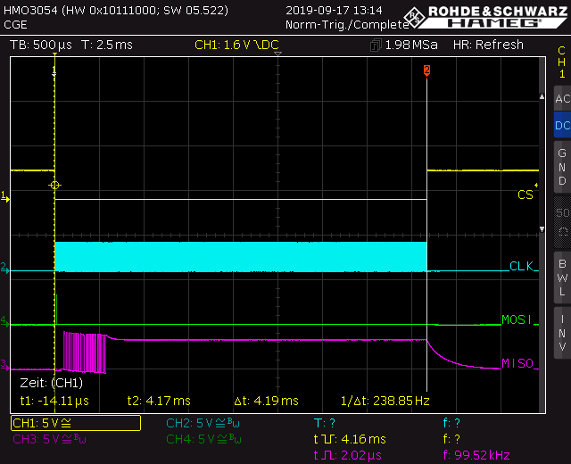
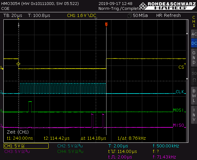
I was very happy, that I successfully complete SPI communication (Program/Read/Erase) with blocking function with ti's SPI Flash Module spi_flash.c and SW-TM4C-UTILS-UG-2.1.4.178.pdf.

For my next step, I would like to work with non blocking function SPIFlashReadNonBlocking().

Is there any example for this? Setting up uDMA, how to handle SPIFlashIntHandler() in the specific interrupt?

In the utils user guide under 18.3 Programming Example there is only a comment (//TODO: Add this).

Thanks for your help,

Regards,

CG

  • Greetings,

    Non-Vendor - young staff here wonders, 'Might it prove wise to Launch "SPIFlashReadNonBlocking()" without the 'entanglement' (likely) to be presented by µDMA?"

    Your early/initial & successful use of the 'SPIBlocking Function' was a perfect example of 'KISS.'     That said - adding complexity 'en masse' - is a clear violation of those guidelines - and subjects you to, 'pain, delay & frustration.'    

    Would not 'Small, Measurable & Verified Steps' - along w/systematic, 'Proceeding by Refinement'  (i.e. 'KISS') - prove very (much) to your advantage?

  • Greetings master guru cb1_mobile,

    I still like your posts in this forum :)

    Okay, I used SPIFlashReadNonBlocking() with param false for bUseDMA ... and it works too.

    So, how do I setting up uDMA if I still want pain, delay & frustration?

  • Christopher Gerner said:
    I still like your posts in this forum :)

    OK already - your check (along with poster John P's) - will shortly be, 'in the mail.'

    Christopher Gerner said:
    I used SPIFlashReadNonBlocking() with param false for bUseDMA ... and it works too.

    Does that not suggest - along w/your claim for 'liking' - that you've 'been here longer' - than your 'point count' reveals?   (20 points = 20 minutes - many believe)

    Vendor's Ralph is far more schooled & expert in 'MCU Specifics' here.     I believe that you may employ the Forum's Search Button - Keywording 'NonBlocking SSI' for starters.    

    You may also search, find & review (many) of the µDMA examples provided - along w/your continuing forum search.

    Staff wishes to know, "How & If you've compared the operational performance between 'Blocking & NonBlocking.'    Much depends upon 'other activity' w/in the MCU - yet for your investigation to 'really prove justified' - such insights ARE required.      

    We look forward to your comments - do cash & spend your check wisely...

  • Yeah, others posts are from our local fae.

    So, I read a lot about usb device stuff and lwip here in this forum.

    I've been working with the controller for two years now and we build a little usb video class device.

    Now I trying to program/read an external spi flash via HID for late use in the mcu.

    I'm not ready with testing, but I simply do some GPIO on/off timing measurements with oscilloscope.

    I will follow your suggestion and searching for the right keyworks.

    Have a nice weekend.

    Thanks for your help,

    Regards,

    CG

  • Aha - did not our 'OTH radar' detect your (stealth) presence ... far beyond '20 minutes?'       Note that such 'Over the Horizon' is a REALLY BIG DEAL...

    Please do, 'Take to heart' - the 'necessity' to conduct proper measurements - so that you can clearly identify, 'IF & When your development efforts (really) are succeeding!)     In itself - this proves 'almost an art' - yet thru practice, high focus & (acquiring expertise) - this measure proves its 'Weight in Gold.'

    Too often - our work w/VC firms reveals - that 'blind belief that 'certain ways' prove better' fails to 'prove out.'     (or just barely improves - or 'devours' time, funds & morale - and the firm then arrives @ VC's doorstep - nearly bankrupt!)    

    Note always that if 'What you seek' is 'unclear' - how will you (ever) know - if you've found it?     Might marketing enable 'false hopes' - which (even) those 'inspired' - may find difficult to deliver?

  • I don't have an example using uDMA with the SPIFlash functions. Let me see if I can come up with something by end of day Monday. 

  • Here is a simple example I came up with. I used the DK-TM4C129x development board. You may ignore the turning on the Green or Blue LED at the end if you are using different hardware. Use the "File" -> "Import" feature of CCS to import this project from the attached .zip file into your workspace.

    /cfs-file/__key/communityserver-discussions-components-files/908/ExtEEPROMuDma.zip

  • Hello Mr Crosby,

    thanks for your effort and for this example.

    I will test it in my workspace and come back if it works or not.

    Best regards,

    CG

  • Okay,

    I had some trouble importing your project because of compiler version 18.12 which I had to install.

    Then the complier not showing up in Window->Preferences->CCS->Build->Compilers

    So I made a new project and copy and past your code.

    I still testing it on my custom board, but I see

    - SPIFlashReadID() correct

    - SPIFlashRead() correct

    - SPIFlashReadNonBlocking(uDMA=false) correct

    - SPIFlashReadNonBlocking(uDMA=true) not working

    Here you can see SPIFlashReadID() from my scope:

    SPIFlashRead() and SPIFlashReadNonBlocking(uDMA=false) looks the same:

    and here SPIFlashReadNonBlocking(uDMA=true):

    I try to save pState->ui16State in the interrupt, so I can see what happen.

    This is what I see:

    STATE_CMD -> STATE_ADDR1 -> STATE_ADDR2 -> STATE_ADDR3 -> STATE_READ_DATA_SETUP -> STATE_READ_DATA_DMA -> STATE_READ_DATA_DMA -> STATE_READ_DATA_END -> STATE_READ_DATA_END

    Any idea?

    Here is my code.

    //*****************************************************************************
    //
    // Copyright (c) 2019 Texas Instruments Incorporated.  All rights reserved.
    // Software License Agreement
    // 
    // Texas Instruments (TI) is supplying this software for use solely and
    // exclusively on TI's microcontroller products. The software is owned by
    // TI and/or its suppliers, and is protected under applicable copyright
    // laws. You may not combine this software with "viral" open-source
    // software in order to form a larger program.
    // 
    // THIS SOFTWARE IS PROVIDED "AS IS" AND WITH ALL FAULTS.
    // NO WARRANTIES, WHETHER EXPRESS, IMPLIED OR STATUTORY, INCLUDING, BUT
    // NOT LIMITED TO, IMPLIED WARRANTIES OF MERCHANTABILITY AND FITNESS FOR
    // A PARTICULAR PURPOSE APPLY TO THIS SOFTWARE. TI SHALL NOT, UNDER ANY
    // CIRCUMSTANCES, BE LIABLE FOR SPECIAL, INCIDENTAL, OR CONSEQUENTIAL
    // DAMAGES, FOR ANY REASON WHATSOEVER.
    // 
    //*****************************************************************************
    
    #include <stdint.h>
    #include <stdbool.h>
    #include "inc/hw_types.h"
    #include "inc/hw_memmap.h"
    #include "inc/hw_ints.h"
    #include "driverlib/sysctl.h"
    #include "driverlib/gpio.h"
    #include "driverlib/interrupt.h"
    #include "driverlib/rom.h"
    #include "driverlib/rom_map.h"
    #include "driverlib/pin_map.h"
    #include "driverlib/udma.h"
    #include "spi_flash.h"
    
    #include "utils/uartstdio.h"
    
    // Defines
    #define LED_GREEN GPIO_PIN_7
    #define LED_BLUE GPIO_PIN_4
    
    
    enum EESTATUS
    {
        NOT_BUSY,
        BUSY
    };
    
    volatile enum EESTATUS eeStatus;
    
    void Ssi1Init(void);
    void intHandlerSsi1(void);
    void uDMAInit(void);
    
    //*****************************************************************************
    //
    // The error routine that is called if the driver library encounters an error.
    //
    //*****************************************************************************
    #ifdef DEBUG
    void
    __error__(char *pcFilename, uint32_t ui32Line)
    {
    }
    #endif
    
    //*****************************************************************************
    //
    // Main 'C' Language entry point.  Toggle an LED using TivaWare.
    //
    //*****************************************************************************
    uint8_t pui8data1[256];
    uint8_t pui8data2[256];
    tSPIFlashState sState;
    //*****************************************************************************
    //
    // The control table used by the uDMA controller.  This table must be aligned
    // to a 1024 byte boundary.
    //
    //*****************************************************************************
    #if defined(ewarm)
    #pragma data_alignment=1024
    uint8_t pui8ControlTable[1024];
    #elif defined(ccs)
    #pragma DATA_ALIGN(pui8ControlTable, 1024)
    uint8_t pui8ControlTable[1024];
    #else
    uint8_t pui8ControlTable[1024] __attribute__ ((aligned(1024)));
    #endif
    
    
    int
    main(void)
    {
        uint32_t ui32SysClock;
        uint32_t i;
        uint8_t ui8ManufacturerID = 0;
        uint16_t ui16DeviceID = 0;
        bool bPass;
    
        //
        // Run from the PLL at 120 MHz.
        //
        MAP_SysCtlMOSCConfigSet(SYSCTL_MOSC_HIGHFREQ);
        ui32SysClock = MAP_SysCtlClockFreqSet((SYSCTL_XTAL_25MHZ |
                                               SYSCTL_OSC_MAIN |
                                               SYSCTL_USE_PLL |
                                               SYSCTL_CFG_VCO_480), 120000000);
    
        // Initialize UART
        MAP_SysCtlPeripheralEnable(SYSCTL_PERIPH_UART0);
        while(!MAP_SysCtlPeripheralReady(SYSCTL_PERIPH_UART0))
        {
        }
        MAP_SysCtlPeripheralEnable(SYSCTL_PERIPH_GPIOA);
        while(!MAP_SysCtlPeripheralReady(SYSCTL_PERIPH_GPIOA))
        {
        }
        MAP_GPIOPinConfigure(GPIO_PA0_U0RX);
        MAP_GPIOPinConfigure(GPIO_PA1_U0TX);
        MAP_GPIOPinTypeUART(GPIO_PORTA_BASE, GPIO_PIN_0 | GPIO_PIN_1);
        UARTStdioConfig(0, 115200, ui32SysClock);
    
        UARTprintf("\033[2J\033[H");
        UARTprintf("\nExtEEPROMuDMA - Test");
    
        // Initialize SSI1
        Ssi1Init();
        SPIFlashInit(SSI1_BASE, ui32SysClock, 500000);
        UARTprintf("\nSPIFlashReadID...");
        //MAP_GPIOPinWrite(GPIO_PORTB_BASE, GPIO_PIN_4, 0);
        SPIFlashReadID(SSI1_BASE, &ui8ManufacturerID, &ui16DeviceID);
        //MAP_GPIOPinWrite(GPIO_PORTB_BASE, GPIO_PIN_4, GPIO_PIN_4);
    
        // read first 256 bytes with a standard read
        UARTprintf("\nSPIFlashRead...");
        //MAP_GPIOPinWrite(GPIO_PORTB_BASE, GPIO_PIN_4, 0);
        SPIFlashRead(SSI1_BASE, 0, pui8data1, 256);
        //MAP_GPIOPinWrite(GPIO_PORTB_BASE, GPIO_PIN_4, GPIO_PIN_4);
    
        // now read using uDMA
        uDMAInit();
        eeStatus = BUSY;
        UARTprintf("\nSPIFlashReadNonBlocking...");
        //MAP_GPIOPinWrite(GPIO_PORTB_BASE, GPIO_PIN_4, 0);
        SPIFlashReadNonBlocking(&sState, SSI1_BASE, 0, pui8data2, 256, true,
                                UDMA_CH11_SSI1TX, UDMA_CH10_SSI1RX);
        //MAP_GPIOPinWrite(GPIO_PORTB_BASE, GPIO_PIN_4, GPIO_PIN_4);
    
        while(eeStatus == BUSY)
        {
            // Loop until read finished
            // Normally do something useful here
        }
        //MAP_GPIOPinWrite(GPIO_PORTB_BASE, GPIO_PIN_4, GPIO_PIN_4);
    
        // Check that both match
        bPass = true;
        for(i = 0; i < 256; i++)
        {
            if(pui8data1[i] != pui8data2[i])
            {
                bPass = false;
                break;
            }
        }
    
        if(bPass)
        {
            UARTprintf("\nOKAY!");
        }
        else
        {
            UARTprintf("\nFAIL!");
        }
    
        while(1)
        {
            // loop forever
        }
    
    
    }
    
    void Ssi1Init(void)
    {
        SysCtlPeripheralEnable(SYSCTL_PERIPH_GPIOB);
    
        // Wait for the GPIO module to be ready.
        while(!MAP_SysCtlPeripheralReady(SYSCTL_PERIPH_GPIOB))
        {
        }
    
        SysCtlPeripheralEnable(SYSCTL_PERIPH_GPIOE);
    
        // Wait for the GPIO module to be ready.
        while(!MAP_SysCtlPeripheralReady(SYSCTL_PERIPH_GPIOE))
        {
        }
    
        SysCtlPeripheralEnable(SYSCTL_PERIPH_SSI1);
    
        // Wait for the SSI module to be ready.
        while(!MAP_SysCtlPeripheralReady(SYSCTL_PERIPH_SSI1))
        {
        }
    
        MAP_GPIOPinConfigure(GPIO_PB5_SSI1CLK);
        MAP_GPIOPinConfigure(GPIO_PB4_SSI1FSS);
        MAP_GPIOPinConfigure(GPIO_PE4_SSI1XDAT0);
        MAP_GPIOPinConfigure(GPIO_PE5_SSI1XDAT1);
    
        MAP_GPIOPinTypeSSI(GPIO_PORTB_BASE, GPIO_PIN_4 | GPIO_PIN_5);
        MAP_GPIOPinTypeSSI(GPIO_PORTE_BASE, GPIO_PIN_4 | GPIO_PIN_5);
    
        // PB4 high - Chip select
        //MAP_GPIOPinTypeGPIOOutput(GPIO_PORTB_BASE, GPIO_PIN_4);
        //MAP_GPIOPinWrite(GPIO_PORTB_BASE, GPIO_PIN_4, GPIO_PIN_4);
    
        IntRegister(INT_SSI1, intHandlerSsi1);
        IntEnable(INT_SSI1);
    }
    
    void uDMAInit(void)
    {
        SysCtlPeripheralEnable(SYSCTL_PERIPH_UDMA);
        while(!MAP_SysCtlPeripheralReady(SYSCTL_PERIPH_UDMA))
        {
        }
    
        uDMAEnable();
        uDMAControlBaseSet(pui8ControlTable);
        uDMAChannelAssign(UDMA_CH10_SSI1RX);
        uDMAChannelAssign(UDMA_CH11_SSI1TX);
    }
    
    void intHandlerSsi1(void)
    {
        if(SPIFlashIntHandler(&sState) == SPI_FLASH_DONE)
        {
           eeStatus = NOT_BUSY;
        }
    }
    

  • Okay,

    I changed

        uDMAChannelAssign(UDMA_CH10_SSI1RX);
        uDMAChannelAssign(UDMA_CH11_SSI1TX);

    to

        uDMAChannelAssign(UDMA_CH24_SSI1RX);
        uDMAChannelAssign(UDMA_CH25_SSI1TX);

    and

        SPIFlashReadNonBlocking(&sState, SSI1_BASE, 0, pui8data2, 256, true,
                                UDMA_CH11_SSI1TX, UDMA_CH10_SSI1RX);

    to

        SPIFlashReadNonBlocking(&sState, SSI1_BASE, 0, pui8data2, 256, true,
                                UDMA_CH25_SSI1TX, UDMA_CH24_SSI1RX);

    and now it works, but why?

  • May we note:

    • gorgeous scope
    • well thought/implemented/labeled and 'consistent' scope-caps

    What induced you to make those changes?    (from Chans: 11 & 10 to 25 & 24)     My group has never used this MCU - yet your 'thought pattern' has generated high interest.

    May we offer (almost) 'Congratulations.'    How sure are you that indeed, 'It works!?'      We are 'hopeful for you' - yet w/out great experience w/this specific µDMA - does your test protocol prove 'sufficient in design' & 'extensive enough' - to catch even (minor) errors?

    (it still would be of immense value to see (via test - contrasting DMA On then Off)  'if & by how much' - this effort paid off...)     Note ... while the µDMA is looping/running - might (some) 'reductions in performance' occur elsewhere w/in the MCU - thus reducing the 'overall gain?'

  • cb1_mobile said:

    May we note:

    • gorgeous scope
    • well thought/implemented/labeled and 'consistent' scope-caps

    Thanks.

    cb1_mobile said:

    What induced you to make those changes?    (from Chans: 11 & 10 to 25 & 24)     My group has never used this MCU - yet your 'thought pattern' has generated high interest.

    I found this post: Link

    He also changed the channels.

    But I think I found the mistake. I use SPI legacy mode on SSI1 and the spi_flash.c functions use advance mode:

    void
    SPIFlashInit(uint32_t ui32Base, uint32_t ui32Clock, uint32_t ui32BitRate)
    {
        //
        // Configure the SPI module.
        //
        MAP_SSIConfigSetExpClk(ui32Base, ui32Clock, SSI_FRF_MOTO_MODE_0,
                               SSI_MODE_MASTER, ui32BitRate, 8);
    
        //
        // Enable the advanced mode of operation, defaulting to read/write mode.
        //
        MAP_SSIAdvModeSet(ui32Base, SSI_ADV_MODE_READ_WRITE);
    
        //
        // Enable the frame hold feature.
        //
        MAP_SSIAdvFrameHoldEnable(ui32Base);
    
        //
        // Enable the SPI module.
        //
        MAP_SSIEnable(ui32Base);
    }

    BUT in errata - spmz850g.pdf under SSI#03 is this:

  • My God man - SO clever, focused & resourceful!    MOST  IMPRESSIVE!

    With that said/acknowledged - should it not be asked that after 'Jumping thru ALL of those Hoops' - what (measurable) benefits have been obtained?

    While such, 'Non-Blocking' operation of an MCU's Peripheral has appeal - does it not arrive w/out (some) trade-offs & compromises?     It is likely that 'much depends' upon  'what's specifically tasked'  of  the MCU - when & while that 'Non-Blocking, µDMA transfer - is 'in process.'    

    It would also be interesting to learn, 'How the µDMA transfer compares 'set-up & duration wise'  vs. the 'Blocking Transfer.'    While the 'results of such comparison are surely 'Application Specific' - they may identify instances where 'Blocking offers key advantages' - and your 'exploitation' of that fact adds value to your 'process'  ...  even though - especially though ... 'unexpected!'

    Thank you for an excellent report - beneficial to others (sure to have missed several of those hoops) - and it is hoped that you'll profit from these focused observations & comments...

    (If interested - we may be able to, 'Outline' that which we believe proves a 'reasonable test' - aimed toward, 'Determining the 'overall impact' (thus (often) effectiveness)'  of 'Blocked vs. Non-Blocked' implementations...)

  • Sorry, I have not been able to find any more details on the erratum SSI#03 to determine if there is any relationship to using DMA channels 10 and 11 instead of 24 and 25. My hardware uses SSI3, so I never saw that issue. But you are correct that the erratum precludes using SSI1 with the SPIFlash routines.