A related question is a question created from another question. When the related question is created, it will be automatically linked to the original question.
If you have a related question, please click the "Ask a related question" button in the top right corner. The newly created question will be automatically linked to this question.
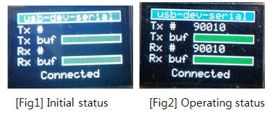
I think the green bar is always full is correct. When it is fully green it means it is empty. If there is some transfer, a portion of the green bar will be filled with red.
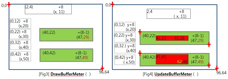
When it is first initialized in the main(), the DrawBufferMeter() is called. If you look at the source code of DrawBufferMeter it has the below code that says the meter is filled with green to indicate empty.
// // Fill the meter with green to indicate empty // GrContextForegroundSet(psContext, ClrGreen); GrRectFill(psContext, &sRect);
// // Put a white box around the meter. // GrContextForegroundSet(psContext, ClrWhite); GrRectDraw(psContext, &sRect);
Please also look at the UpdateBufferMeter() API where the portion or all of the green bar is filled with red depending on the transfer status.
// // Fill the full section with red (if there is anything to draw) // if(ui32FullPercent) { GrContextForegroundSet(psContext, ClrRed); GrRectFill(psContext, &sRect); }
// // Fill the empty section with green. // sRect.i16XMin = i32XBreak; sRect.i16XMax = i32X + BUFFER_METER_WIDTH - 2; if(sRect.i16XMax > sRect.i16XMin) { GrContextForegroundSet(psContext, ClrGreen); GrRectFill(psContext, &sRect); }
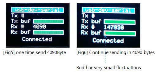
The color bar just tries to reflect how many data are available in either the TX or RX USBbuffer. I don't really see a problem with it. I see the RED color changing from left to right. Note that the UpdatBufferMeter is only updated when there is any transmit or receive traffic from the perspective of the UART. You can try to transfer a large amount of data (i.e. a text file) from the USB to the UART. You will see the Tx bar changing rapidly.
Please bear in the mind the difference between the USB and UART in terms of their buffer size. The USB bulk transfer at full-speed can buffer 64 bytes of data while the UART has a much smaller FIFO buffer (i.e. 16). Therefore, the the UpdateBufferMeter will be called more often (much quicker like 4x faster) when the UART is receiving than when the USB port is receiving. Note for the RX bar, the ui32Fullness is relative to the UART's receive buffer.
            //
            // Update the TX buffer fullness. Remember that the buffers are
            // named relative to the USB whereas the status display is from
            // the UART's perspective. The USB's transmit buffer is the UART's
            // receive buffer.
            //
            ui32Fullness = ((USBBufferDataAvailable(&g_sTxBuffer) * 100) /
                          UART_BUFFER_SIZE);
            UpdateBufferMeter(&g_sContext, ui32Fullness, 40, 42);
Your understanding is correct except that the UART_FIFO_TX4_8 is to interrupt at half (8 bytes out of 16 bytes) of the FIFO or 50%. Therefore, the USBUARTintHandler will be called 8 times more quickly compared to when the USB is receiving/transmitting.
Please go to the uart.h file for the MACRO definition.
//*****************************************************************************
//
// Values that can be passed to UARTFIFOLevelSet as the ui32TxLevel parameter
// and returned by UARTFIFOLevelGet in the pui32TxLevel.
//
//*****************************************************************************
#define UART_FIFO_TX1_8         0x00000000  // Transmit interrupt at 1/8 Full
#define UART_FIFO_TX2_8         0x00000001  // Transmit interrupt at 1/4 Full
#define UART_FIFO_TX4_8         0x00000002  // Transmit interrupt at 1/2 Full
#define UART_FIFO_TX6_8         0x00000003  // Transmit interrupt at 3/4 Full
#define UART_FIFO_TX7_8         0x00000004  // Transmit interrupt at 7/8 Full

//*****************************************************************************
//
// Values that can be passed to UARTFIFOLevelSet as the ui32RxLevel parameter
// and returned by UARTFIFOLevelGet in the pui32RxLevel.
//
//*****************************************************************************
#define UART_FIFO_RX1_8         0x00000000  // Receive interrupt at 1/8 Full
#define UART_FIFO_RX2_8         0x00000008  // Receive interrupt at 1/4 Full
#define UART_FIFO_RX4_8         0x00000010  // Receive interrupt at 1/2 Full
#define UART_FIFO_RX6_8         0x00000018  // Receive interrupt at 3/4 Full
#define UART_FIFO_RX7_8         0x00000020  // Receive interrupt at 7/8 Full
Crack staff notes the 'uncanny' resemblance between Pumpkin #1 & cb1. (cb1 on a 'good' day... yet that pumpkin somehow 'avoided' cb1's '1000 yard stare!') Thankfully there's no sign of the: peg-leg, nervous tic/twitch nor ankle bracelet/monitor. (staff told you - the judge did not like me...)
Let the record show that 'long ago' - cb1's (baby) 'Serrated Incisors' fetched 'Top Dollar' from the tooth fairy. Newly implanted ones were *LIKED* - both by Staff & Great Whites. (sharks ... as we share the same 'serrated implant team'...)
Our 'back-room' office (somehow) becomes 'popular' each Halloween. (Staff - enticingly costumed as: French Maids, Stern Nurses, & Witches - may raise our firm's profile - at least for that day ... )
Tag: NO: '5x5 fonts, Live-Updated List Boxes, nor black cats' - were harmed during the creation of this (LIKE-free) post...
What - has 'your' thread now descended to another, 'Barren & Pumpkin-Free' Zone? Where's the uniqueness/spirit in that?
Staff notes that the pumpkin you shipped us, 'Arrived Fine' - yet the passage of time - has NOT been Kind! (Staff here notes that (now) both your pumpkin - and 'cb1' - (due to slight aging) must receive 'extreme treatment!' (i.e. 'Reconstructive Plastic Surgery' and 'Hope not high' - for either...)
TAG: 'Masks' may 'Not be required' - for some at our shop - Next Halloween...
Please refer to the usbbuffer.c and usbdcdc.c under <TivaWare_Installation>/usblib for the source code. You will find USABufferRead() and USBBufferWrite().
Be sure to thank Vendor's Charles for his quick & complete answer! (Re: his clear guidance: USABufferRead() and USBBufferWrite().)
It is assumed that the 'Salad Bowl Filled to Overflowing' - includes a nice slab of rare, 'Filet Mignon' - entombed (briefly) beneath the vegetable brigade. We 'growing boyz' need 'real protein' - you realize.
Staff arrives in about 20 minutes - they'll advise/inform re: your UART_TX concerns... (And they will certainly 'NOTE' your inclusion of a 'Proper, Post Summarizing Tag' - rather than the default (oh so feeble - non descriptive) one...)
Having 'stumbled in' - crack crüe reports(this gleaned directly from the '123's) Manual:
"For transmission, data is written into the transmit FIFO. If the UART is enabled, it causes a data frame to start transmitting with the parameters indicated in the UARTLCRH register. Data continues to be transmitted until there is no data left in the transmit FIFO."
and
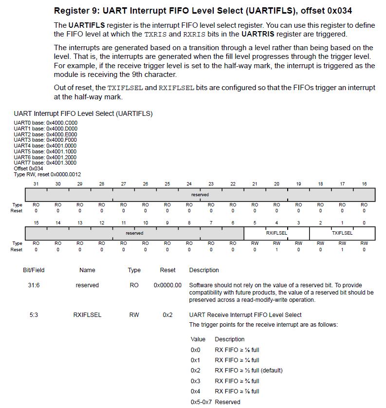
"The trigger points at which the FIFOs generate interrupts is controlled via the UART Interrupt FIFO LevelSelect (UARTIFLS) register (see page 922). Both FIFOs can be individually configured to trigger interrupts at different levels. Available configurations include ⅛, ¼, ½, ¾, and ⅞."
Now - to your specific questions:
1) "When data is written to TxFIFO, will it be automatically sent to UART0 Tx pin immediately?" What is your definition of 'immediately?' (that's important - is it not?) Without enabling the FIFO - staff notes (near) immediate output from UARTn_TX. (this observed via O-Scope)
2) "Is it sent to UART0 Tx based on the interrupt level 50% setting in FIFO memory?" The manual never specifically relates the link between UART Output & the Interrupt Level. (or - staff & I could not (easily) find it.) It is suspected that the UART_TXn output is 'Not Held Hostage' by the Interrupt Level - you should be able to devise a simple test to confirm. (Staff is not lazy - this serves as a good 'learning tool' for you...)
Cb1 Said > What is your definition of 'immediately?' (that's important - is it not?)
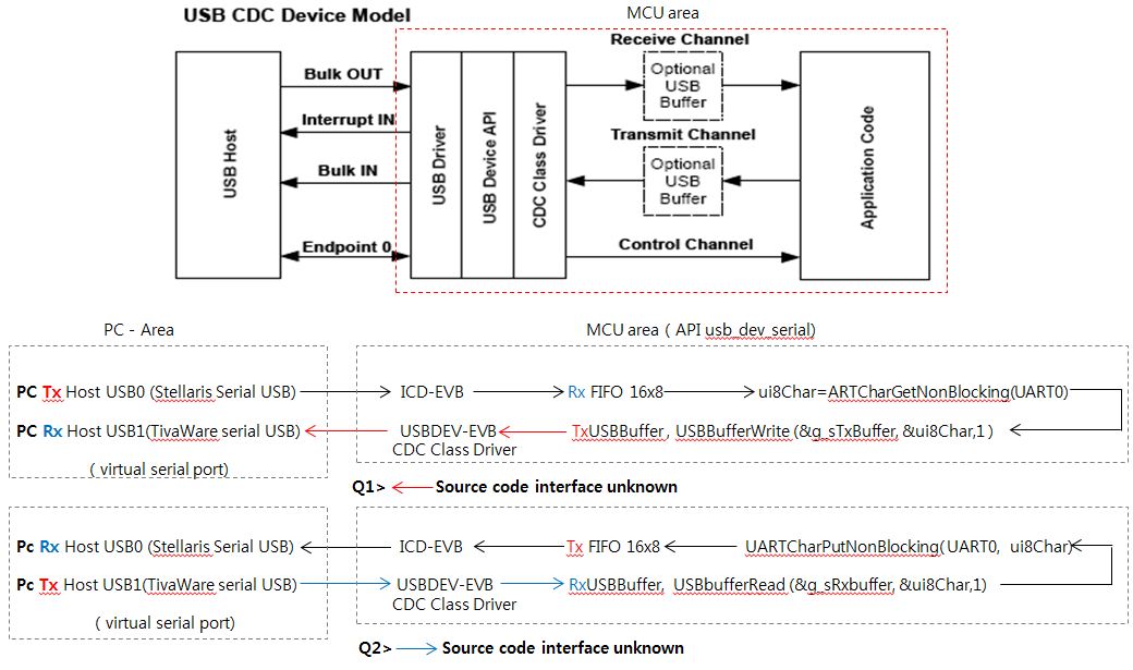
A> In the usb_dev_serial API, UART_FIFO_TX4_8 is enabled with half of the FIFO (8 bytes out of 16 bytes) or 50% interrupt configuration
Cb1 Said > Without enabling the FIFO - staff notes (near) immediate output from UARTn_TX. (this observed via O-Scope)
A> i.e. Sending 1 byte character from USB1 transmission serial terminal immediately receives 1 byte character from USB0 receiving serial terminal.
Q1> In the words of Cb1 and staff, if the FIFO is enabled, does it wait for 8 bytes in the FIFO and then print it to the next USB0( via ICD) receiving terminal window?
( self-reflection , My thoughts and actions are lazy, Don’t have O-Scope now)
Greetings to this forum's 'Artistic Director.' And while your creativity (likely) 'pain some' - you've added LIFE to an otherwise 'barren plain.'
Even though it is just past 08:00 Sunday - and only 3 staffers have 'come in' - we all (suddenly) have become hungry! (that 'thanks' (somehow) to forum's Artistic Director!)
Not having a Scope places you at a, 'Real Disadvantage' - especially when you are deployingSerial Interfaces. (i.e. SPI, I2C, CAN - most notably)
That said - is not one 'Creative & Resourceful enough to present 'Filet Mignon' to this (otherwise) 'Cut/Paste Plain' - able to 'IMAGINE' a 'Scope Replacement/Substitute'?'
Now the Scope presents two key advantages:
Notes the presence or absence of Signal(s)
Reveals the, 'Sequence of Signal Arrival' - often in great detail
Often allows the (reasonably) accurate, 'timed-measurement' of:
signal width
recognition of signals' 'timed relationship' to one another
and sometimes extends to 'Frequency & Duty Cycle' measurement & display
Now - to answer your particular questions - are not 'ONLY' the toa 'Time of Arrival' (and even) 'IF the signal arrives' - your REAL ISSUES?
Young Staff here believes, 'That is so' - thus can a Signal's 'Arrival/Presence' be (somehow) detected - yetminus a Scope?
Staff - having 'hacked' your 'Artistic File' (at least in 'spirit') - present:
as a beyond, 'Adequate Scope Substitute' when 'Signal Presence, Generation (and or Pulsation)' proves of interest and/or value.
While 'timing' infoappears unavailable - it too can be 'gleaned' via (imaginative):
'Feeding back your Signal - 'UARTn_TX' (in this case)
to, 'One (several - even better) of the MCU's (many) Timer pins'
throw in some 'minimal 'Timer Programming'
which 'THEN' enables 'Timed Measurements' - without ANY SCOPE ...
TAG: When 'NO Scope' proves 'NO EXCUSE!' (now that's a 'proper Tag!')
Q1> In the words of Cb1 and staff, if the FIFO is enabled, does it wait for 8 bytes in the FIFO and then print it to the next USB0( via ICD) receiving terminal window?
Regardless in FIFO mode or not, as soon as you write to the FIFO, the transmission will start. There is a 16 bytes deep TX FIFO. The threshold to generate the TX interrupt is programmable. Let's suppose you program the TX interrupt FIFO trigger level to 1/2. This means that the interrupt is only generated after there are 8 bytes or less in the FIFO. The processor could have written 16 bytes to the TX FIFO in a burst. After the first byte is written to the TX FIFO, the transmission starts. You should see the START bit on the UART TX pin immediate if you use the scope to capture. After 8 bytes are transmitted out, there is only 8 bytes left in the FIFO. This is the time when the TX FIFO interrupt is generated to notify the processor write more data to the TX FIFO.
May it be noted - that such 'highly similar' data 'WAS' previously presented to this poster?'
cb1_mobile said:
Having 'stumbled in' - crack crüe reports(this gleaned directly from the '123's) Manual:
"For transmission, data is written into the transmit FIFO. If the UART is enabled, it causes a data frame to start transmitting with the parameters indicated in the UARTLCRH register. Data continues to be transmitted until there is no data left in the transmit FIFO."
and
"The trigger points at which the FIFOs generate interrupts is controlled via the UART Interrupt FIFO LevelSelect (UARTIFLS) register (see page 922). Both FIFOs can be individually configured to trigger interrupts at different levels. Available configurations include ⅛, ¼, ½, ¾, and ⅞."