Tool/software: Code Composer Studio
Thank you for sharing your code, I have downloaded and studied it.
I have a few doubts about it and I will be pleased if you help me with them. To test your code, I connect a potentiometer in PE2, varying from 0V (GND) to 3.3V (GPIO of the board).
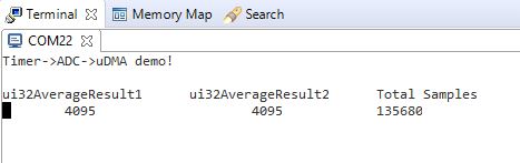
1)I understood that the ADC_Outs are the vectors that are receiving data from the ADC. But I could not understand the pattern of the numbers. The majority of them are ZERO even if PE2 is 3.3V. I thought it should be 4096 = 2^12(number of bit of ADC0). Could you explain to me the math?
2) Why have you used many zeros as 0u. What is this "u" for? Can I remove it?
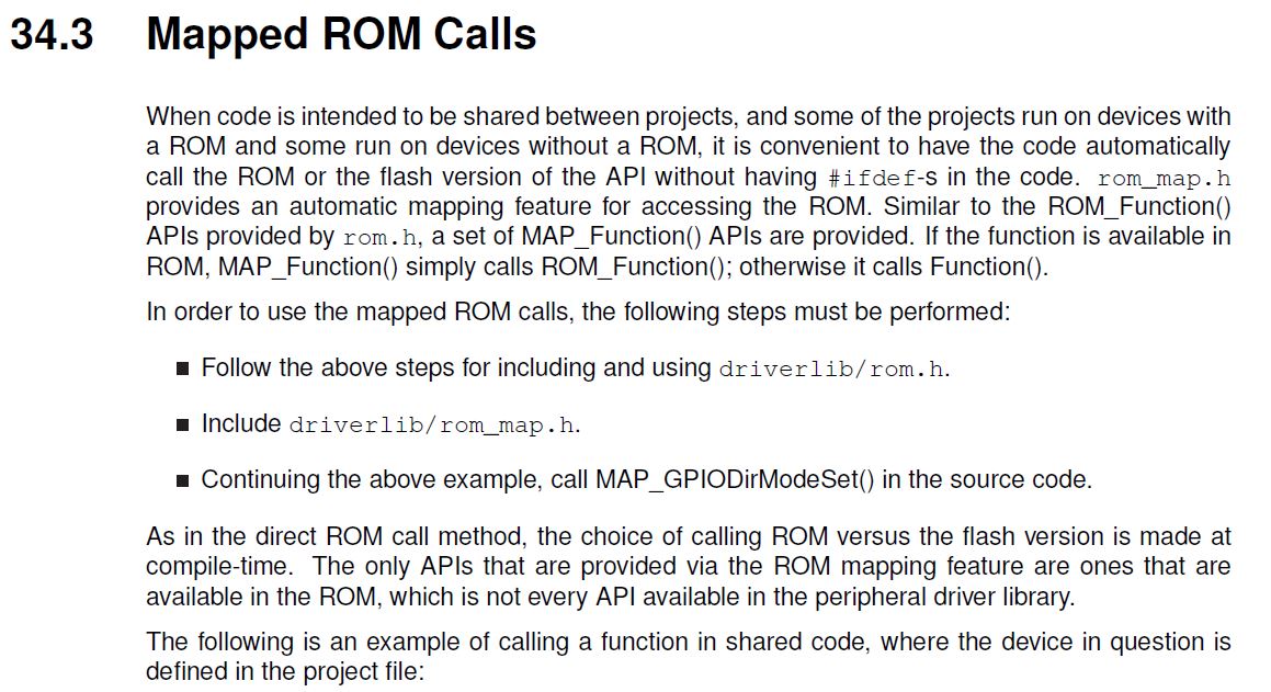
3) I noticed some functions of driverlib (TivaCSeries)with the prefix MAP_. Why have you done that? Can I remove it?
My aim is to pick a voltage signal from a GPIO. The real project is a filter but for tests, I have connected a potentiometer in PE2 (pin of ADC0). I want to grab the values in a choosing rate and make operations with them.
For example, my potentiometer is set in 3.3V. I want to grab this vector (for me the numbers of the vector should be at least similar) and make operations with it. For instance, I can multiple it by 2 or multiple the vector by a constant matrix.
I am a beginner with microcontrollers, so if you have other tips or materials to help me, it will be of great value.
I am looking forward to your reply. If you prefer a different channel of communication, I am also open.
Thanks!