This thread has been locked.

If you have a related question, please click the "Ask a related question" button in the top right corner. The newly created question will be automatically linked to this question.

TM4C123FH6PM: Configuring PWM for driving a transformer

Part Number: TM4C123FH6PM
Other Parts Discussed in Thread: EK-TM4C123GXL

Good day!

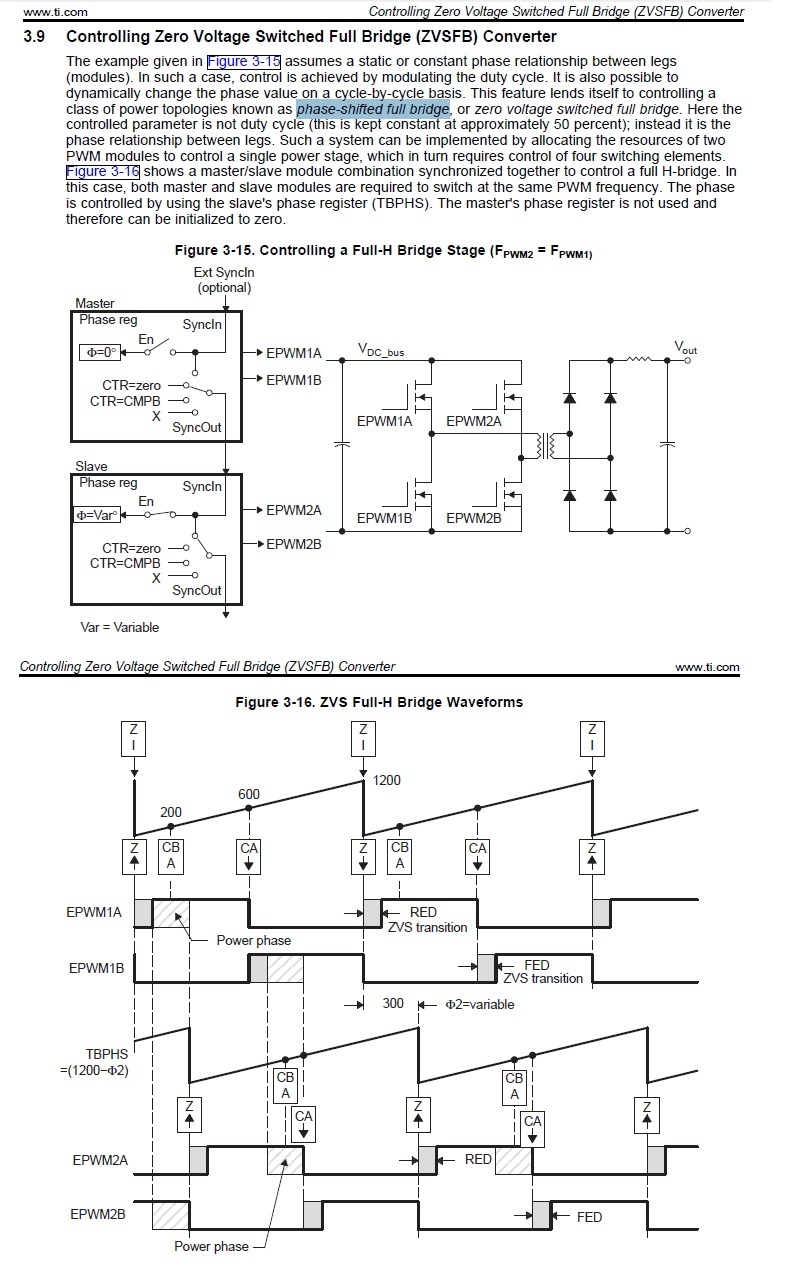
I need to drive a transformer with two PWM signals using H-bridge. So I need these two signals to interleave, as first will drive positive bridge state and second will drive negative.

As I see from datasheet, I need to configure PWM in up-down mode, and to trigger pwmA signal high on zero, and trigger it low on compare up, then trigget pwmB signal high on load and trigger it low on compare down.

But I do not see in TivaWare DriverLib a way to configure these trigger events, could you please help me?

Thank you!

  • Take a look at the TivaWare example in "C:\ti\TivaWare_C_Series-2.2.0.295\examples\boards\ek-tm4c123gxl\pwm_dead_band". 

  • C:\ti\TivaWare_C_Series-2.1.4.178\examples\boards\ek-tm4c123gxl>dir
    Том в устройстве C не имеет метки.
    Серийный номер тома: FCE2-1E79

    Содержимое папки C:\ti\TivaWare_C_Series-2.1.4.178\examples\boards\ek-tm4c123gxl

    12.05.2019 19:58 <DIR> .
    12.05.2019 19:58 <DIR> ..
    12.05.2019 19:58 <DIR> bitband
    12.05.2019 19:58 <DIR> blinky
    12.05.2019 19:58 <DIR> drivers
    12.05.2019 19:58 3 520 ek-tm4c123gxl.eww
    12.05.2019 19:58 2 951 ek-tm4c123gxl.uvmpw
    12.05.2019 19:58 <DIR> freertos_demo
    12.05.2019 19:58 <DIR> gpio_jtag
    12.05.2019 19:58 <DIR> hello
    12.05.2019 19:58 <DIR> interrupts
    12.05.2019 19:58 1 961 Makefile
    12.05.2019 19:58 <DIR> mpu_fault
    12.05.2019 19:58 <DIR> project0
    12.05.2019 19:58 <DIR> qs-rgb
    12.05.2019 19:58 <DIR> timers
    12.05.2019 19:58 <DIR> uart_echo
    12.05.2019 19:58 <DIR> udma_demo
    12.05.2019 19:58 <DIR> usb_dev_bulk
    12.05.2019 19:58 <DIR> usb_dev_gamepad
    12.05.2019 19:58 <DIR> usb_dev_serial
    3 файлов 8 432 байт
    18 папок 21 293 465 600 байт свободно

    There is no "pwm_dead_band".

  • I see, that version I use is older than 2.2.0.295.

    Anyway, in 2.1.4.178 the same example is located in C:\ti\TivaWare_C_Series-2.1.4.178\examples\peripherals\pwm, and this example does resolve my question. It just uses dead band generation to ensure the PWM signals does not overlap, but it is not a task. I need both signals to be the same, but on different phases, as I need to set up PWM rate. To be exact, I need the waveform:

    |-------|_________________ PWMA

    ___________|-------|______ PWMB

    where length of pulses is the same for both signals and adjustable online, as I measure transformer output.

  • Hi Oleg,

    You might need to do HWREG register calls to control A/B comparators for the H bridge. The code below configures complementary generator outputs A/B. Below C2000 HBridge post here for required comparator actions and drive layout. Past forum posters mention TM4C PWM and ZVSFB if you search for info may show up.

    * Configure PWM0 for center aligned complementary GENA/GENB drives */

    HWREG(PWM0_BASE + PWM_O_1_GENA) = (PWM_X_GENA_ACTCMPAU_ONE | PWM_X_GENA_ACTCMPAD_ZERO);
    HWREG(PWM0_BASE + PWM_O_1_GENB) = (PWM_X_GENB_ACTCMPAU_ZERO  | PWM_X_GENB_ACTCMPAD_ONE);
    HWREG(PWM0_BASE + PWM_O_2_GENA) = (PWM_X_GENA_ACTCMPAU_ONE | PWM_X_GENA_ACTCMPAD_ZERO);
    HWREG(PWM0_BASE + PWM_O_2_GENB) = (PWM_X_GENB_ACTCMPAU_ZERO  | PWM_X_GENB_ACTCMPAD_ONE);


  • Thanx, so as I see there no API function in DriverLib for configuring PWM events.

    As my task is simplier - I am using an IC for driving MOSFETS, and this IC has 2 inputs, I just configured 2 PWM signals to work with desired duty cycles in different phases.

  • Hi Oleg,

    Getting two generators to produce complementary output signals rather than overlapping signals requires the comparators be properly configured. The problem with overlapping basic generator configuration are not meant to specifically drive H bridge. Even if two PWM signals (PWM-A/B) or generators, likely will produce different duty cycle (if periods are similar) since they are overlapping signals.

    Placing HWREG commands after generator configure will change the overlapping comparator outputs into non-overlapping complementary pairs.  I think that is important in a push/pull H bridge in order to simulate sinusoidal wave forms. Two NFETS on and Two NFETS off on any given period but generators must be synchronous and exactly at the same duty cycles or the sine wave will be distorted looking.