Hi Team,
Our customer would like to get clarifications in the section 4.1 of System Design Guidelines for SimpleLink MSP432E4 Microcontrollers document (SLAA770).
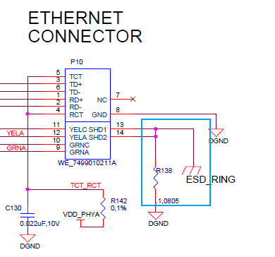
It describes the external circuitry required for the ethernet internal PHY. The diagram included in Figure 29 includes this circuitry. Connected to the part RJ45 are a resistor and capacitor (R44 and C38). From their design research, they have always seen a high rated capacitor connected between the chassis ground and MCU ground but have never seen a resistor connected in such a way, linking the different grounds.
They are wondering if they could get some clarification or explanation on the purpose of R44 and whether it is necessary for this design.
Also, if the ground labeled "chassis" is equivalent to earth ground (third prong on an outlet).
Thanks,
Jonathan
-
Ask a related question
What is a related question?A related question is a question created from another question. When the related question is created, it will be automatically linked to the original question.


