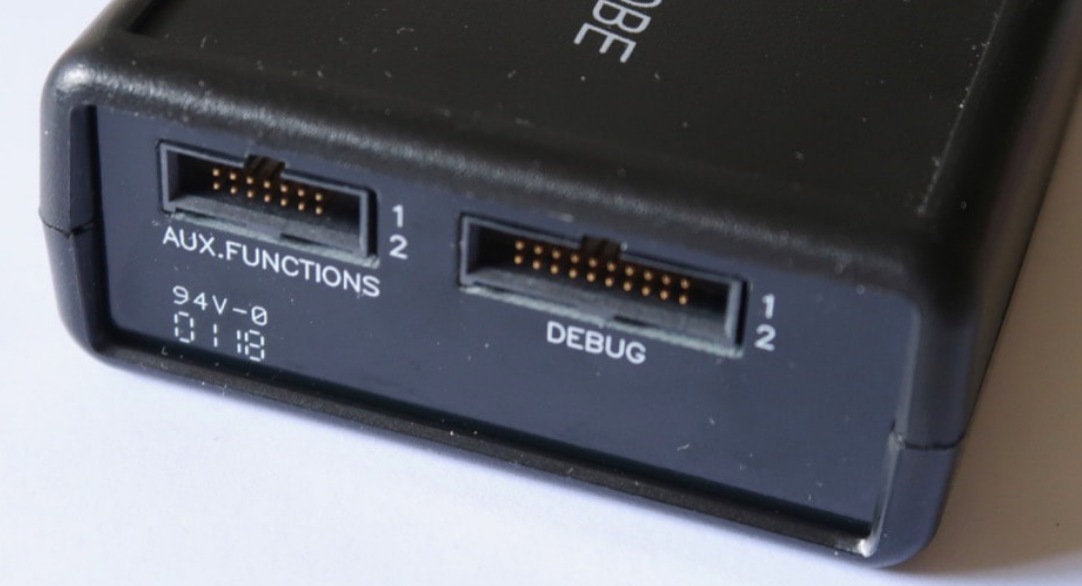
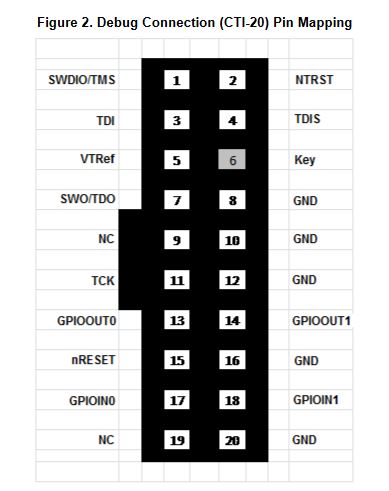
Please tell me if the diagram shows the pins considering the FRC is at the back or FRC at the front side. I want to know the direction of FRC.
Please tell me if the diagram shows the pins considering the FRC is at the back or FRC at the front side. I want to know the direction of FRC.