This thread has been locked.

If you have a related question, please click the "Ask a related question" button in the top right corner. The newly created question will be automatically linked to this question.

TM4C129XNCZAD: Example code for TM4C129X

Part Number: TM4C129XNCZAD
Other Parts Discussed in Thread: EK-TM4C1294XL

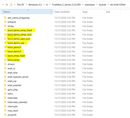
We need example code for Flash bootloader not ROM bootloader which will work on TM4C129X development board. We are using TM4C129XNCZAD controller in our design.

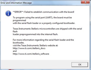
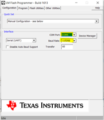
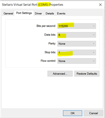
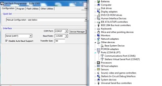
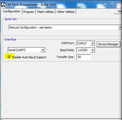
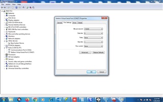
I am using LM flash loader for practicing with TM4C129X board.

  • HI,

      There are several flash bootloader examples in TivaWare library. 

      You can find these examples in C:\ti\TivaWare_C_Series-2.2.0.295\examples\boards\ek-tm4c1294xl. The boot_serial and boot_emac_flash are bootloader while the rest are applications to be bootloaded from. Please also refer to the bootloader user's guide for details. www.ti.com/.../spmu301

    If you are interest in CAN bootloader there is a also an application note with examples.

    https://www.ti.com/lit/pdf/spna245

  • Hi charles,

    Tm4c129x Development board

    I have dump the boot_serial @0x0000 through LM Flash loader and modified Bl_config.h contain application address @ 0x4000

    Now Build  one application @0x4000 and through LMFlash loder with uart option tried to dump the code with offset 0x4000 but

    we get error" Failed to establish communication with the board" 

  • Hi,

      Several things to check. Did you choose the correct COM port? Did you choose the correct baud rate? See below LM flash programmer. In my setting, I have COM5. You may have other COM port shown up after USB enumeration. 

    Go to your Windows device manager and make sure the COM port (in my case COM5) has the correct settings. 

  • Dear Charles,

    Double Checked,NO issue with configuration But still getting above mentioned  error. Configuration attched for refernce

  • Hello,

      In the device manager, can you right click on COM27 and make sure its baudrate setting is indeed 115200 with one stop bit and no parity? See the image I uploaded in my last reply. 

      If it still does not work, can you unclick the "Disable Auto Baud Support" like below which I also showed in my last reply. Does it make a difference?

  • Charles ,

    I have already tried above thing but sorry not posted in my post. 

    With or without tick No success

  • Hi,

    I have dump the boot_serial @0x0000 through LM Flash loader and modified Bl_config.h contain application address @ 0x4000

    Now Build  one application @0x4000 and through LMFlash loder with uart option

    I just want to clarify some things here. You said you modified the bl_config.h and build your application. Can you clarify what you change in the bl_config.h file? 

    Can you try the TivaWare examples as is. Do not modify anything. In the TivaWare there is already a boot_serial (this is a bootloader) and there are two applications (boot_demo1 and boot_demo2) that are to be loaded by the bootloader. The bl_config.h was already configured for bootloading via UART. There is no need to modify anything if you try the TivaWare examples as they are. Can you please try them and are you getting the same problem? You can find the bootloader in C:\ti\TivaWare_C_Series-2.2.0.295\examples\boards\ek-tm4c1294xl\boot_serial and the application in C:\ti\TivaWare_C_Series-2.2.0.295\examples\boards\ek-tm4c1294xl\boot_demo1. Again there is no need to modify anything. These examples are proven. If they don't work on you then it will be the PC side to look at. 

    Can you try on another computer?

    Can you show me your device manager display?

    Can you probe the UART0TX and UART0RX pins? When the PC sends the command to the MCU, you should see some activities on the UART0RX pin? What do you see?

  • I have tried as you suggested.

    I again install 2.2.0.295 package .

    I have dump whatever boot_serilal.bin file available in above package through LM flash loader+Jtag@0x0000 location. Successful

    After that choose Manual configuration and baud 115200+serial uart and dump boot_demo1.bin @0x4000.succesful

    After that again choose  manual configuration and baud 115200+serial uart and dump boot_demo2@ 4000  but getting same error .

    I have Stellerais LM3S9B96 development board. I have apply the same procedure i.e boot_serial,boot_demo1,boot demo2 (file available with stellaris package) and Its working with stellearis board

    But the same procedure not working with TM4C129X

    The TM4C129X uses part no. TM4c129XCNzaD wherer as the folder you suggested is tm4c1294xl. Is that make any diffrence?

  • Hi,

      Sorry, I thought you were using EK-TM4C1294XL launchHpad. Looks like you are using the DK-TM4C129x EVM board. Is it correct? Please confirm if you have a EK-TM4C129xXL launchPad that you can run the boot_serial and boot_demo1/boot_demo2. The boot_demo1 expects the SW1 to be pressed on the LaunchPad to bootload another program. However, the switch on the LaunchPad will be different compared to the DK EVM board. You can modify it youself or If you only have the DK EVM board then please refer to this below post where Ralph provided an example application to be run on the DK EVM board. 

     https://e2e.ti.com/support/microcontrollers/other/f/other-microcontrollers-forum/987359/tm4c129xnczad-bootloader-with-tm4c129x

     I'm attaching the application again.

    5751.boot_demo_uart_flash.zip

  • Dear Charles,

    I am using TM4C129X Development board.

  • Hi,

      Understand that you are using the TM4C129X development board. Again, did you have a chance to use the modified boot_demo_uart_flash.zip that was attached in my last reply?

  • Hi Charles,

    First I have dump the boot_serial.bin through LM flash loader with Jtag  at program offset 0x00 . Successfully.

    I dump boot_demo_uart_slash code as suggested through LM Flash loader with manual configuration+serial uart at program offset 0x4000

    Then it works " it displayed the bit information on screen" .It means it works.

    Now i have dump my code through LM Flash loader with manual +serial uartat program offset 0x4000. Code imported succesfully but nothing displayed on screen .

    For cross checking I  dump my code using LMflash with jtag at program offset 0x0000 then  content display on screen.

    What can be the issue?

    Is offset is not matching??

    Is issue with my process which i am following for code dumping.

    8473.New_Error_Calculator.zip

  • Hi,

    I dump boot_demo_uart_slash code as suggested through LM Flash loader with manual configuration+serial uart at program offset 0x4000

    Then it works " it displayed the bit information on screen" .It means it works.

    Glad that it works. 

    Now i have dump my code through LM Flash loader with manual +serial uartat program offset 0x4000. Code imported succesfully but nothing displayed on screen .

    So it proves the bootloader works. But your application may have problem. How did you develop your application. Did you develop your application with the code starts at 0x0 or at 0x4000? 

    For cross checking I  dump my code using LMflash with jtag at program offset 0x0000 then  content display on screen.

    It seems to suggest that you develop your application at 0x0. You cannot do that. You must develop your application with the linker setting that relocate the application image at 0x4000. Look at the linker file of the boot_demo_uart_flash example. The bootloader starts at 0x0. When the bootloader starts, it checks to see if there is an application image at 0x4000. If there is an image at 0x4000, then the bootloader will jump to it to run the application. Now you have an application that is "programmed" to 0x4000 but that image actually starts at 0x0 instead of 0x4000. 

  • Dear Charles ,

    Thanks . I have modified the linker start address  and its working.

    The boot_serial is work on UART 0. I want to use UART1 . If i will modify the boot_serial bi_uart.c as per UART1 then it will work on ?

    Or suggest what other file need to be modify

  • Hi,

      Yes, you just need to modify from UART0 to UART1 and it should work. However, please bear in mind that the EVM board only has the UART0 routed to the ICDI debug probe for COM port. If you want to use UART1, you need to have a USB to UART bridge chip.

  • Dear Charles ,

    Understood.

    While dumping code purposely power off the device  then not able to communicate to LM flash loader.

    How to  resolve /avoid this issue in programming?

  • Hi,

      Please refer to the Bootloader user's guide for detail on the CRC function. https://www.ti.com/lit/pdf/spmu301. The idea is that if you lose power in the middle of bootloading then the firmware may only be partially programmed. When you power up or reset the device again, the bootloader will check if you have correct CRC value. If not, it will try to bootload your firmware again. 

    These posts may also be helpful.

    https://e2e.ti.com/support/microcontrollers/other/f/other-microcontrollers-forum/953150/tm4c123gh6pge-bootloader-corrupted-not-working-properly-after-the-device-power-down-when-flashing/3522062#3522062